Abstract
We present a study of the influence of magnetic field strength and morphology in Type Ia supernovae and their late-time light curves and spectra. In order to both capture self-consistent magnetic field topologies and evolve our models to late times, a two-stage approach is taken. We study the early deflagration phase (∼1 s) using a variety of magnetic field strengths and find that the topology of the field is set by the burning, independent of the initial strength. We study late-time (∼1000 days) light curves and spectra with a variety of magnetic field topologies and infer magnetic field strengths from observed supernovae. Lower limits are found to be 106 G. This is determined by the escape, or lack thereof, of positrons that are tied to the magnetic field. The first stage employs 3D MHD and a local burning approximation and uses the code Enzo. The second stage employs a hybrid approach, with 3D radiation and positron transport and spherical hydrodynamics. The second stage uses the code HYDRA. In our models, magnetic field amplification remains small during the early deflagration phase. Late-time spectra bear the imprint of both magnetic field strength and morphology. Implications for alternative explosion scenarios are discussed.
1. Introduction
Thermonuclear supernovae (SNe), or SNe Type Ia (SNe Ia), are explosions of white dwarfs (WDs; Hoyle & Fowler 1960). They are important for understanding the universe and the origin of elements and are a powerful tool for measuring large distances. They are also laboratories for understanding the physics of flames, hydrodynamic instabilities, radiation transport, nonequilibrium systems, and nuclear and high-energy physics in regimes not accessible by ground-based experiments. Here we examine the impact of magnetic fields on SNe Ia, which may alter the sphericity, nuclear burning front, light curves (LCs), and spectral properties.
While SNe Ia LCs can be used as “quasi-standard candles” (Phillips 1993), there is growing observational evidence for spectral diversity among SNe Ia that may impact their accuracy as distance measures and, thus, the use of SNe Ia for precision cosmology. This has prompted subclassifications based on observational characteristics, e.g., high- and low-velocity SNe Ia (Benetti et al. 2005), shallow, core-normal, broad Si lines, or cool SNe Ia (Branch et al. 2005). These classifications are widely used for modern data sets (Branch et al. 2009; Folatelli et al. 2013; Wang et al. 2013). The source of these spectral differences may come from similar but aspherical objects that are seen from different angles (Höflich et al. 2006; Motohara et al. 2006; Maeda et al. 2010; Shen et al. 2018), or they may indicate differences in progenitor or explosion scenarios (Hoeflich & Khokhlov 1996; Quimby et al. 2006; Shen et al.2010; Polin et al. 2019). Likely, it is a combination of both.
A WD, left alone, will eventually cool to the background temperature of the universe. For the WD to explode, it must interact with a close companion during the progenitor evolution leading to the explosion. The companion may either be another WD (a double-degenerate, DD, system) with a short orbital period or a nondegenerate star (a single-degenerate, SD, system), such as a main-sequence, helium, or red giant star.
While the exact scenario or scenarios leading to the explosion are still under study, they can be classified by three distinct mechanisms that trigger the explosion. These are slow compressional heating, surface helium detonations, and the merger of two WDs. The first happens on long timescales, while the latter two occur quickly. We will discuss each of these in turn.
In the first explosion scenario, the WD accretes material from a companion in either a DD system on long timescales, so-called secular mergers, or an SD system (Whelan & Iben 1973; Piersanti et al. 2003). The explosion is triggered by compressional heat close to the center of the WD when approaching the critical Chandrasekhar mass, MCh. The flame propagates by deflagration (Nomoto & Thielemann 1984) and, more likely, starts as a (subsonic) deflagration and transitions to a (supersonic) detonation (deflagration-to-detonation transition, DDT). The transition from deflagration to detonation is likely due to the mixing of burned and unburned matter, called the Zeldovich mechanism (Khokhlov 1995a; Niemeyer et al. 1996). The mixing process can be understood in terms of the Zeldovich gradient mechanism (Brooker et al. 2021) or a unified turbulence-induced mechanism that makes DDT unavoidable (Poludnenko et al. 2019) at densities suggested by observations. See Höflich et al. (2013) for a detailed discussion.
In the second explosion scenario, a surface helium detonation (HeD) 3 triggers a detonation of a sub-MCh WD with a C/O core (Woosley et al. 1980; Nomoto 1982; Livne 1990; Woosley & Weaver 1994; Hoeflich & Khokhlov 1996; Kromer et al. 2010; Sim et al. 2010; Woosley & Kasen 2011; Shen & Moore 2014; Glasner et al. 2018; Tanikawa et al. 2018; Townsley et al. 2019). For triggering the initial detonation, these models require an unmixed surface He layer of ≈10−2...−1 or ≈5 × 10⁻³...−2 M⊙ with assumed mixing of carbon into the helium layer on microscopic scales.
In the third possible scenario, two WDs merge or collide. This process occurs on a dynamical timescale, much faster than the slow accretion timescales from the previous processes (Iben & Tutukov 1984; Webbink 1984; Benz et al. 1990; Rasio & Shapiro 1994; Hoeflich & Khokhlov 1996; Segretain et al. 1997; Yoon et al. 2007; Lorén-Aguilar et al. 2009; Wang et al. 2009b, 2009a; Isern et al. 2011; Pakmor et al. 2011, 2012). In simulations of this process, the ejecta show large-scale density asymmetries.
It should also be mentioned that any of these triggering mechanisms can be realized within the common envelope of an asymptotic giant branch (AGB) star and a WD. This has been invoked to explain superluminous SNe Ia—the so-called super-MCh explosions. Here the degenerate C/O core of the AGB star can explode in two ways. Either the core grows by accretion on secular timescales from a disrupted WD and compressional heat triggers the thermonuclear runaway, or the degenerate AGB core merges with the WD on a dynamical timescale (Hoeflich & Khokhlov 1996; Yoon et al. 2007; Kashi & Soker 2011; Hoeflich 2017; Hsiao et al. 2020).
The predominant mechanism for “normal” SNe Ia is still under debate, with favorites changing with time. As we will discuss in the conclusions, nuclear physics dominates the final outcome of the explosion, and successful models result in almost overlapping progenitor mass ranges among different scenarios.
In our study, we examine the impact of magnetic fields on several aspects of SNe Ia in the classical delayed-detonation scenario because this allows us to reproduce LCs and spectra of classical SNe Ia. The results will be put into the context of other explosion scenarios in the final discussion and conclusions.
Our study is based on and combines two previous papers. Hristov et al. (2018, hereafter Paper I) showed the magnetic field effects on nuclear burning fronts in a rectangular tube. Penney & Hoeflich (2014, hereafter Paper II) studied the effect of magnetic fields for dipole and turbulent morphologies on positron transport, which showed the presence of high magnetic fields (B-fields) in some observed SNe. The goal of this paper is to extend and combine these studies for full star simulations with initial conditions that allow one to reproduce observations and to test the basic assumption on the field morphology in Paper II.
The obvious question concerns the origin of high B-fields. While some WDs are observed with B of several 107 G, the majority have no measurable field (Liebert et al. 2003; Schmidt et al. 2003; Silvestri et al. 2007; Tout et al. 2008). As will be discussed in the conclusion, high B would require field amplification (a) by rotation-induced circulation; (b) during the smoldering phase, which is characterized by convection-driven nonexplosive carbon burning, with large eddy sizes corresponding to the pressure scale height in the WD (Hoeflich & Stein 2002); or (c) during the dynamical phase of the explosion considered here.
For the DDT mechanism, one of the crucial problems is how to partially suppress the strong Rayleigh–Taylor (RT) instabilities during the explosion (Khokhlov 1995b; Niemeyer & Kerstein 1997; Gamezo et al. 2003a; Röpke 2005; Hoeflich 2006; Motohara et al. 2006; Penney & Hoeflich 2014; Diamond et al. 2015; Galbany et al. 2019; Yang et al. 2019). This instability forms when low-density, high-temperature material is accelerated into higher-density material. The acceleration is most commonly a gravitational field but can also be bulk acceleration. The instability manifests as a pattern of rising mushroom-like structures of low-density burned material, leading to large-scale mixing. In particular, 3D hydrodynamical simulations predict rising plumes throughout the entire WD (Gamezo et al. 2003a; Röpke 2005). Although plumes at the RT scales have been observed in SN remnants (Fesen et al. 2007) and indicated by high-resolution polarization spectra of SNe Ia (Patat et al. 2012; Yang et al. 2019), they are very constrained in velocity space. High magnetic fields are known to suppress the RT instability (Chandrasekhar 1961), and as a WD is a fully ionized plasma, it is reasonable to consider the effect of magnetic fields (Remming & Khokhlov 2014; Paper I).
In Paper I, we simulated a 240 km × 15 km × 15 km tube of constant density with WD conditions with magnetic fields from 109 to 1012 G. Our finding was that the development of RT instability was partially suppressed at a magnetic field strength of 1010 G and almost completely suppressed at 1012 G. In most cases, this was related to a reduction in the overall burning rate. However, in certain configurations of the burning front and magnetic field (namely, models Z12 and YZ12, where the field is strong and aligned with the propagation direction), the front speed and the thickness of the burning region are increased relative to the unmagnetized case. In this configuration, the field maintains a thicker burning region, and the increased burning increases the speed of the front. If this configuration manifests in a real star, it may give another route to the DDT.
Paper II studied the effect of magnetic fields for dipole and turbulent morphologies on the positron transport and found that fields can greatly impact the late-time LCs and line profiles. The size of the effect greatly depends on the morphology of the field. In previous studies, the magnetic fields have been assumed to be (a) radial or locally trapping small-scale fields (Milne et al. 2001) or (b) dipoles or arbitrary turbulent fields (Höflich et al. 2004).
The trapping of positrons by magnetic fields can be observed as an increase in brightness in the late-time LC and the width and evolution of certain atomic line profiles. Between 300 and 1000 days after the explosion, the primary energy source in the SN is positrons produced by the decay of 56Co. If the positrons are trapped by the magnetic field, the SN will remain brighter than if they are allowed to freely diffuse away from their birthplace. The degree of trapping depends on both the morphology and strength of the magnetic field and has been the subject of several PhD theses (Milne & Leising 1999; Penney & Hoeflich 2014). For LC studies, Milne et al. (2001) calculated positron transport for radial magnetic fields and assumed that, for turbulent fields, all positrons are locally trapped.
In Paper II, we used small-scale turbulent and dipole fields as representations of large fields. We showed that positrons are not locally trapped, even for turbulent fields. The results depend on the size, scale, and morphology of the field. We also showed that magnetic fields and subsequent positron trapping can also impact late-time near-infrared (NIR) spectra. Specifically, we focused on the 1.644 μm feature, which is dominated by a single [Fe ii] transition, rather than consisting of other blended features in the optical and NIR (Hoeflich et al. 2004; Diamond et al. 2015). After about day 300, the shape of the line profile provides important information about the distribution of 56Ni, including asymmetries, which may in part come from magnetic fields (Hoeflich et al. 2004; Motohara et al. 2006; Diamond et al. 2015; Maguire et al. 2018). Using this line, lower limits for the magnetic field in the SN 2003du field were found to be 5000 G using analytical approximations for the positron transport (Hoeflich et al. 2004). Detailed positron transport calculations and observations of NIR line profiles suggest lower limits larger by 1–2 orders of magnitude.
The 1.644 μm line also opened a new aspect and further motivates our focus on DDT models. While the line offset may be influenced by the peculiar velocity of the progenitor system relative to the host galaxy (typically 100 km s−1 ), it also reflects the orbital velocity of the binary system. Narrow binary systems result in large offsets in velocity, whereas wide binary systems (and lower velocity offsets) are expected when the companion star is nondegenerate. Though the statistics is small, the offset shift (v < 500 ... 1000 km s−1) of the feature in several SNe Ia (SN 2003du, Hoeflich et al. 2004; SN2005df, Diamond et al. 2015; SN2014J, Diamond et al. 2018; SN2012ht, SN2013aa, and SN2012cg, Maguire et al. 2018) suggests the existence of wide progenitor systems rather than the narrow systems to be expected for SD progenitors. Two possible exceptions are SN 2012fr and SN 2013cf (Maguire et al. 2018), which show velocities consistent with DD progenitors (Shen et al. 2018). Both narrow and wide systems can lead to MCh explosions, whereas mergers and HeD models can only originate from close binaries with large velocities.
This work extends and connects two prior studies with a focus on the morphology and size of the magnetic field. Namely, it tries to answer the following questions. Do the conclusions from simulations in the box still hold up for full stars with density gradients? Does a deflagration phase change the morphology of an initial dipole field? Can the high magnetic fields be produced during the early deflagration phase? What constraints can be put on the size of the magnetic fields in the progenitor without arbitrarily assuming its morphology?
The goal of this paper is to study the effect of magnetic fields on the explosion and the observational consequences. For computational feasibility, we do not present a single end-to-end simulation for the entire evolution but strive to perform two interconnected and consistent sets of simulations. In the first part, we assume the size of the magnetic field and determine its morphology from simulation. In the second part, we assume the morphology of the magnetic field and constrain its size from LCs. It is important to address the question of whether observations can constrain the magnetic field into the regime where they cannot be neglected.
Here we run two stages of simulations. For consistency, we start with a WD structure, which allows us to reproduce observations, and consistent equations of state throughout all phases. The first stage extends the study of Paper I to a 3D star to include large-scale wave modes. The ability of the magnetic field to suppress instability is a function of the wavelength of the perturbation. In Paper I, we used a small rectangular domain, which restricted perturbations to those that can fit across the box, 15 km. While we were able to completely suppress RT, larger wavelengths may still be unstable. This stage uses 3D magnetohydrodynamics (MHD), with the size of B as a free parameter and a simplified burning model, starting from the stage at which RT instabilities are known to develop. The second stage extends Paper II by employing the magnetic field topology from a more realistic model, namely, the simulations of the first stage. In the second stage, we study the impact of magnetic field strength and topology on positron escape in the late stages (1000 days) of LCs and line profiles to constrain the size of the initial B-field. This stage uses 1D radiation hydrodynamics, a more complete nuclear network of 218 isotopes, time-dependent non-local thermodynamic equilibrium (NLTE) models for atomic-level populations, and 3D photon and positron transport. We assume that the magnetic topology is set by the deflagration phase, and that the postdetonation dynamics are entirely determined by the explosion. We then simulate the LC as described in Hoeflich et al. (2017b), with the addition of a 3D magnetic field that is passively advected along with the (homologous) expansion of the SN. This allows us to more accurately capture the behavior of the positrons while remaining computationally feasible.
Our paper is organized as follows. In Section 2, we will describe the numerical methods employed and the setup of the simulations. In Section 3, we will discuss the stage 1 results of the early deflagration and the morphology of the field. In Section 4, we will present stage 2 and address the impact of magnetic fields on late-time spectra and LCs. In Section 5, we will discuss the results and implications for the scenario-dependent observables. We summarize our results, discuss the possible sources of amplification, and briefly address the differences between MCh and helium-triggered explosions.
2. Method
Our two stages of simulations both begin from the same hydrostatic WD. The initial model for all simulations in both stages is based on model 23 from Hoeflich et al. (2017b).
The first stage is restricted to the early deflagration phase; this phase explores the impact of magnetic fields on the burning and examines the evolution of the topology of the magnetic field. This stage follows the nondistributed regime of burning in three dimensions with 3D MHD.
The second stage also begins from model 23 and follows the SN Ia to late times, examining the impact of magnetic field strength and topology on the transport of positrons and the resulting effect on LCs and spectra. Stage 2 uses a hybrid approach, employing distributed burning in 1D, while the 3D magnetic field is passively carried with the explosion. To initiate the magnetic field in the second stage, we map the magnetic field from stage 1 onto a spherical comoving grid. We follow the evolution to the phase of free expansion. This two-stage approach allows us to use full MHD when the magnetic field is thought to be dynamically important and create self-consistent magnetic topologies but also follow the LC for much longer than possible for an explicit 3D MHD simulation.
The first stage, discussed in Section 2.1.2, uses the 3D MHD code Enzo (Bryan et al. 2014). For the second stage, discussed in Section 2.2.2, we use our NLTE code for 3D HYDrodynamical RAdiation transport (HYDRA). The results are discussed in Sections 3 and 4, respectively.
2.1. Stage 1: Initial Deflagration
2.1.1. WD Setup
Each of our four stage 1 simulations begins with a hydrostatic WD with a central density of 1.15 × 10⁹ g cm−3 and an initial radius of 1975 km. To seed the burning instability, we begin with the central region initially burned in a starlike pattern. We superimpose a magnetic dipole oriented along  at the origin. The only parameter that changes between the four models is the dipole moment magnitude, i.e., the strength of the magnetic field. The Cartesian domain is 4000 km3, with outflow boundaries on all quantities.
Model parameters are chosen to resemble the physical conditions of a WD after the onset of the deflagration stage, while the burning is still in the nondistributed regime. We interpolate from model 23 to the higher-resolution 3D grid using a Taylor series for the density and pressure, subject to the requirement to fit the original profiles and derivatives at the innermost points.
The internal energy is initialized to maintain hydrostatic equilibrium in the unmagnetized case. The value of the adiabatic index, γ = 1.35, was chosen to be consistent with stage 2. This choice is based on the equation of state as implemented in HYDRA (see Appendix B and Paper I). The result is a radial pressure profile, not including magnetic pressure, from which we construct the internal energy profile. Owing to the combination of the mismatch between the spherical structure and Cartesian grid and the magnetic pressure, we are left with small residual velocities within the inner 100 km, which we discuss further at the end of this section.
Most of the star is pure fuel (50:50 carbon/oxygen). We initialize a burning front at the center (100% 56Ni). To build the burning front, we first triangulate a sphere with radius 200 km with 80 facets, then add 200 km fingers on each facet. A projection of this starlike pattern can be seen in Figure 1.
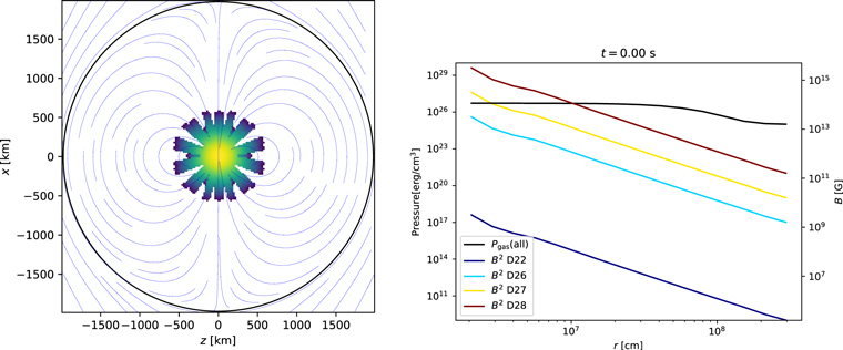
Figure 1. Initial configuration. (Left) Projection of the initially burned region and magnetic field lines. The black line shows the edge of the star at 1975 km. The initially burned material is distributed in fingers radiating from the center. A total of 80 fingers starting 200 km from the center and length 400 km are used. This initial configuration is identical for all four simulations, with only the strength of the field changing. (Right) Initial thermal pressure (black line) and magnetic pressures vs. radius for all four simulations. The black line shows the pressure profile (identical for all runs), while the colored power-law lines show the magnetic pressure (left axis) or field strength (right axis).
Download figure:
Standard image High-resolution imageThe initial magnetic field is a global magnetic dipole with a moment along the x-axis. To ensure that the divergence of the magnetic field is numerically zero, we initialize the vector potential and take its curl to produce the magnetic field. The vector potential is

where  . The initial dipole moments M are 1022, 1026, 1027, and 1028 G cm−2. We refer to each simulation by the order of magnitude of the dipole moment, that is, D22, D26, D27, and D28, respectively; see Table 1. The initial magnetic topology can be seen in the left panel of Figure 1. The angle-averaged magnetic profile can be seen in the right panel of that figure, which shows the magnetic and gas pressure (left axis) and magnetic field strength (right axis).
Table 1. Model (Run) Names versus the Strength of the Initial Magnetic Field, B
| Model Name | Magnitude of the Initial |
|---|---|
| Magnetic Dipole Moment | |
| [G cm−2] | |
| D22 |

|
| D26 |

|
| D27 |

|
| D28 |

|
Download table as: ASCIITypeset image
There are two extraneous sources of acceleration in our setup: the first from errors in mapping the spherical star to the Cartesian grid and the second from our non-force-free magnetic configuration. These accelerations are confined to the inner 100 km, which is well within the initially burned region and only imparts a small amount of excess kinetic energy. It should be noted that simply offsetting the magnetic pressure by reducing the gas pressure is insufficient, as the magnetic tension B · ∇ B must also be initially zero. This must be done numerically. While force-free magnetic fields should be used in future experiments, the perturbation here is not large enough to affect our conclusions.
2.1.2. Stage 1 Method: Enzo
For the first stage of simulations, we use the code Enzo (Collins et al. 2010; Bryan et al. 2014) modified for nondistributed burning. The code is designed for astrophysical applications supporting a number of physics processes, including MHD. It solves the Eulerian equations of ideal MHD, as well as the nondistributed burning equations, which are




Here
v
v
and
B
B
are the velocity and magnetic field outer products, and ρ,
g
, and  are the density, gravitational acceleration, and rate of energy production from the nuclear burning. Further, E = e + ρ
v2/2 + B2/8π is the total energy density, and P = p + B2/8π is the total pressure.
are the density, gravitational acceleration, and rate of energy production from the nuclear burning. Further, E = e + ρ
v2/2 + B2/8π is the total energy density, and P = p + B2/8π is the total pressure.
The following equation of state closes the system:

To speed the calculation and reduce numerical instability, the gravitational acceleration, g , is computed from the spherically averaged density,

To check the validity of this assumption, we tested this solver against the fast Fourier transform–based gravity solver in Enzo using the strongly magnetized (and least round) case. Deviations between the two were at most 1% at the outer boundary and ≪1% in the interior.
In the nondistributed burning approximation, we assume that the width of the burning front is small compared to a zone, and that the fuel is burned instantaneously to produce a specific energy, Q. Our burning operator is based on Khokhlov (1995a). In this model, the flame propagates via diffusion of the molar burned fraction, f,

where f = 0 is pure fuel, and K and R are the diffusion rate and reaction rate, respectively. Here  if f is between the threshold for burning, f0 = 0.3, and unity, when no burning is possible, and zero otherwise. The constants are chosen such that the front diffusion speed
  . The energy produced by the nuclear burning,
  , needed in Equation (4), is calculated as

where  is the nuclear energy released per gram of fuel, and ρprod is the partial mass density of the burned product. The relation between f and ρburn can be seen in Equation (A7) in Appendix A.
We use the constrained transport MHD module in Enzo (Collins et al. 2010; Bryan et al. 2014). We have shown that this method preserves ∇ · B = 0 to near machine precision. For the primary evolution of the MHD equations, we use Li et al. (2008) and the HLLD Riemann solver of Mignone (2007). To compute the electric field, the constrained transport method of Gardiner & Stone (2005) is used.
2.2. Stage 2: Late-time Evolution
We wish to study the impact of magnetic field strength and topology on the transport of positrons in late-time (∼1000 days) SNe and their impact on LCs and spectra. We show that there is a measurable increase in late-time LCs (∼0.5m ) if the positrons are locally trapped by the magnetic field, rather than the unmagnetized case, which allows for positrons to more freely diffuse out of the core. This can be used to estimate lower limits on magnetic field strengths of published SNe; see Section 4.
2.2.1. Remapping and Hybrid Model
The cost of continuing the Enzo simulations until t = 1000 days is computationally prohibitive; one of these simulations took several days on 64 processors to compute 1 s of time. As there are 8 × 10⁷ s in 1000 days, continuing the run would surely extend past the end of the funding period. Moreover, the physics needed to follow the explosion beyond the phase of nondistributed burning are not currently available in Enzo. Much success has been had by employing 1D simulations, which can afford more complete physics packages (Hoeflich et al. 2017b). However, the diffusion of positrons is a fundamentally 3D process, being dependent on the strength, topology, and distribution of the magnetic field. Thus, for stage 2, we adopt a hybrid approach, where the hydrodynamics is solved in 1D (assuming spherical symmetry), while the positron transport is 3D. The 3D magnetic field is taken as a passive tracer and expands in a frozen-in manner with the expanding SN.
The core assumption is that the magnetic field topology is determined during the subsonic deflagration phase, and the dynamics during the supersonic detonation phase are determined exclusively by the overwhelming explosion energy. We show in Section 3 that only the strongest magnetic field has any impact on the burning front; the three more reasonable cases are quite spherical and have similar topologies, which justifies our neglect of the back-reaction of the magnetic field on the burning in stage 2. While it is possible that the topology may continue to evolve after the detonation, it is unlikely that the field will become less tangled or be further amplified. As the decay timescale for a magnetic field in a fully ionized WD with temperature T = 109 K is 109 yr (see, e.g., Choudhuri 1998), it is unlikely that substantial decay will take place in the few hundred days examined here. Thus, passive advection of the magnetic field is sufficient for our purposes here.
The stage 2 simulations begin from the same spherical WD as the stage 1 simulations and make use of our NLTE code for HYDRA. Since the mechanism of DDT is not established, it is treated as a free parameter. The DDT is initiated by mixing of 0.01 M⊙ at the burning front. In this simulation, the DDT is triggered after burning of about 0.27 M⊙, corresponding to a transition density of 2.5 × 10⁷g cm−3. Unlike some previous studies (Hoeflich 2006; Fesen et al. 2007), we will not consider an off-center delayed-detonation transition (Hoeflich 1990, 1995a, 2003a, 2003b; Diamond et al. 2015; Telesco et al. 2015; Hoeflich et al. 2017b). This technique produces LCs and spectra that are consistent with normal-bright SNe Ia (Hoeflich et al. 2017b). The addition in this current work is the improvement of the positron transport.
We should note that an attempt was made to directly map the results of stage 1 to the 3D hydrodynamics models in HYDRA. The structure is close to hydrostatic, and Pgas is many orders of magnitude larger than Pmag (see Figure 1). However, omitting even a small magnetic pressure caused numerical instability on the grid scale, crashing the simulations. Thus, we use this more simplified approach.
2.2.2. Stage 2 Method: HYDRA
For the stage 2 simulations, we use our NLTE code for HYDRA. Here we briefly outline the modules included. For more details, see Appendix B.
The simulations begin with a spherical hydrostatic C/O WD identical to that of stage 1 (Hoeflich et al. 2017b). The simulations utilize a nuclear network of 218 isotopes during the early phases of the explosion; detailed, time-dependent NLTE models for atomic-level populations; and γ-ray and positron transport and radiation hydrodynamics to calculate low-energy LCs and spectra (Hoeflich 1995a, 2003a; Penney & Hoeflich 2014).
The results use spherical hydrodynamics until 10 days after the explosion. During the ongoing deflagration phase, the rate of burning is parameterized based on physical flame models and calibrated to 3D hydrodynamical models by A. Khokhlov (Khokhlov et al. 1997; Domínguez & Hoeflich 2000; Gamezo et al. 2005). The decay of 56Ni increases the specific energy corresponding to a velocity of ≈3000 km s−1 over the course of its half-life, 6.1 days. This ongoing energy input requires the hydrodynamics and time-dependent radiation transport equations to be solved simultaneously in order to properly treat cooling by the PdV term. For this early phase, we solved the radiation transport equations in comoving frames using ≈100 frequency groups. The simulation uses atomic models with ≈106 line transitions taken from the compilations of Kurucz (1993), supplemented by forbidden-line transitions of iron-group elements in the lower ionization states (Telesco et al. 2015).
After 10 days, the hydrodynamical evolution is assumed to be homologous expansion, v ∝ r. This is adequate because the kinetic energy dominates all other energy sources, and the sound speed is many orders of magnitude smaller than the expansion velocity.
For computational efficiency, we did not recalculate the photosphere and transitional phase of expansion but skipped to the nebular phase starting at day 100.
Magnetic fields impose the necessity of 3D treatment for the positron transport and, with it, the 3D radiation transport for both high- and low-energy photons. For the stage 2 simulations discussed here, we use the 3D Monte Carlo modules for the photon and positrons.
Because of the assumptions above, we use angular averaged departure coefficients, i.e., the relative population number of the atomic levels relative to its ground state within each ion. This is justified because the infrared (IR) radiation originates from optically thin layers, and luminosities become isotropic. We assume stationary radiation transport; i.e., we neglect the implicit time dependence in the transport terms for photons and positrons and in the rate equations. For details, see Appendix B.
We restrict our discussion to day 1000 because after that, additional radioactive isotopes (e.g., 57Co, 55Fe, 44Ti) are expected to dominate the energy input, giving a natural limit for our study.
3. Stage 1 Evolution: Morphology and Burning Rate during the Early Deflagration Phase
3.1. Burning and RT
The evolution of the nickel density for each of our four simulations can be seen in Figure 2. The top row of figures has the weakest magnetic field, while the bottom has the strongest. Time increases to the right, from the initial condition to t = 0.6 s. In each simulation, the burning proceeds outward, retaining an imprint of the initial perturbation. It is notable that the magnetic field has little impact on the nickel distribution for any but the most strongly magnetized simulations.
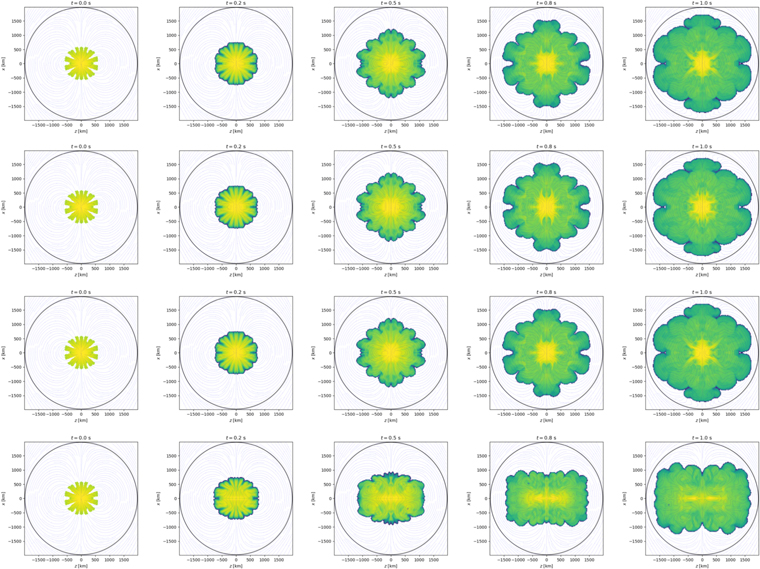
Figure 2. Slices of nickel density for all four simulations. Magnetic field strength increases downward, and time increases to the right. Only the most strongly magnetized case shows appreciable modification to the flow morphology.
Download figure:
Standard image High-resolution imageGas heated by the burning subsequently develops rising fingers of magnetized gas due to the RT instability. This is seen in the magnetic field distributions in Figure 3, which shows slices in the most weakly and strongly magnetized simulations, D22 and D28, respectively, at t = 0.6 s. Due to flux freezing, the magnetic energy that is initially strongest in the center is dragged upward with the heated “low-”density gas. The instability, and the correlation between the magnetic field and the low-density gas, is most evident in the strongly magnetized run; see the bottom left panel of Figure 3. This is counter to our initial expectation, which was that the strongest magnetic field would suppress the RT instability (Chandrasekhar 1961; Paper I). Here RT seems to be more pronounced in the most strongly magnetized run.
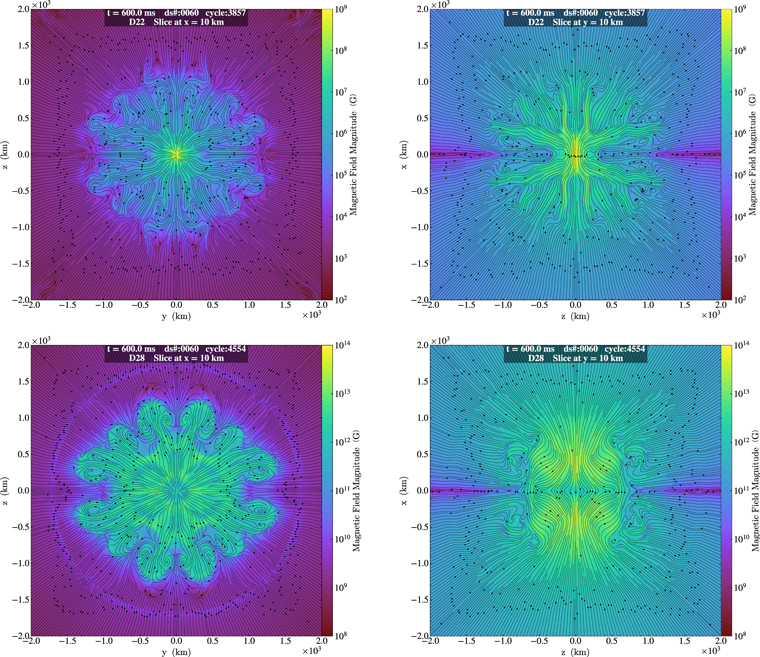
Figure 3. Magnetic field strength and streamlines. In our weak-B model, D22 (top row), the magnetic field develops eddies following the RT instabilities. The structure of the initial global magnetic dipole is almost lost. It requires a much higher initial B, as in D28 (bottom row), to survive the RT instabilities. Since the latter magnitudes are unrealistic, this agrees with the lack of observational evidence for directional dependence, suggested by models in non-DDT scenarios.
Download figure:
Standard image High-resolution imageThis extra RT can be explained in part by the extra energy released during the settling of the initial conditions. Figure 4 shows the energy densities for each of the four simulations (with red, yellow, cyan, and blue in order of decreasing magnetic field strength). Black solid lines show the gas pressure, colored solid lines show magnetic energy, and colored dotted lines show kinetic energy. The pressure profile for each can be seen with the black dashed line. The pressure profile evolves very little during this evolution and is nearly the same for each of the simulations. At t = 0 s, the magnetic energy is below the gas pressure for all radii for the two weakly magnetized fields. The two more strongly magnetized runs have a small excess of magnetic energy. The excess magnetic energy is released in the first 0.01 s and in turn drives a somewhat larger flow than that seen in the other two simulations. It can also be seen that in the strongly magnetized run, D28, the magnetic and kinetic energies are roughly balanced over all radii by t = 0.05 s. For the other simulations, kinetic energy due to the burning outweighs magnetic energy at outer radii. It is interesting to note that even though the magnetic energy is large in D28, there is still a clearly defined RT. This shows that equipartition of magnetic and kinetic energies is not a sufficient criterion for suppression of hydrodynamical instabilities.
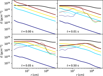
Figure 4. Energy vs. radius for the first 0.5 s. Here we show magnetic energy density (solid lines), gas pressure (black solid lines), and kinetic energy density (dotted lines) averaged over the sphere. Time increases to the right. The simulations D22, D26, D27, and D28 are color-coded as red, yellow, cyan, and blue, respectively, as in Figure 1. As the pressure profiles are nearly identical, we plot only one for clarity.
Download figure:
Standard image High-resolution imageIt can be seen in the bottom row of Figure 2 that the burning nickel in the most magnetized run is flattened along the poleward direction. This is due mainly to the anisotropic magnetic pressure, which is larger along the poles. Only in D28 is this pressure large enough to alter the burning.
3.2. Tangling
The structure of the magnetic field, while initially a dipole, is quickly tangled by the kinetic motions of the gas. This can be seen clearly in Figures 3 and 5, which show the magnetic field lines for the two extreme cases. The magnetic field structures clearly follow the density structures, becoming substantially more tangled. This is due to the action of flux freezing, whereby magnetic flux is pinned to the moving fluid.
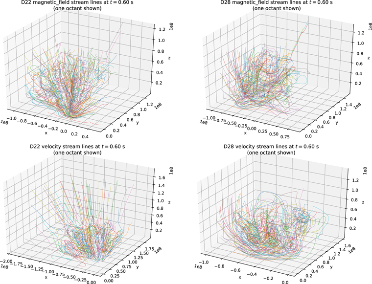
Figure 5. Magnetic field line “hairballs.” In our weak-B model, D22 (left column), the velocity field develops RT instabilities, and the magnetic field eddies follow. The structure of the initial global magnetic dipole is almost lost. It requires a much higher initial B, as in D28 (right column), to survive the RT instabilities. Since the latter magnitudes are unrealistic, this shows why there is no observational evidence of directional dependence, suggested by models in non-DDT scenarios. For clarity, the figures show field lines originating in the x < 0, y > 0z > 0 octant only.
Download figure:
Standard image High-resolution imageIn order to quantify the degree of tangling in the magnetic and velocity fields, we use the autocorrelation functions  and
and  of the respective direction vectors,
  and
and  :
:


These functions measure the degree to which the fields  and
and  are correlated with themselves at a separation of Δ
x
. The interior integration is an average over the domain V. The outer integration is over the direction of the shift Δx, so the functions depend only on the magnitude of the shift and not its direction. The above functions are normalized so that AC(0) = 1. At zero separation, anything is perfectly correlated with itself. A field with more spatial disorder, and hence increased tangling of the fields, will show a lower correlation with itself at a certain distance. Figure 6 shows the autocorrelation function for our dipole (labeled t = 0), which shows a nearly linear decrease in the correlation with distance. On the same graph, a “maximally disordered” configuration of driven high Reynolds number MHD turbulence (blue line) is shown for comparison. The more tangled turbulent state shows lower autocorrelation, despite being statistically spatially homogeneous, due to the chaotic nature of turbulence.
are correlated with themselves at a separation of Δ
x
. The interior integration is an average over the domain V. The outer integration is over the direction of the shift Δx, so the functions depend only on the magnitude of the shift and not its direction. The above functions are normalized so that AC(0) = 1. At zero separation, anything is perfectly correlated with itself. A field with more spatial disorder, and hence increased tangling of the fields, will show a lower correlation with itself at a certain distance. Figure 6 shows the autocorrelation function for our dipole (labeled t = 0), which shows a nearly linear decrease in the correlation with distance. On the same graph, a “maximally disordered” configuration of driven high Reynolds number MHD turbulence (blue line) is shown for comparison. The more tangled turbulent state shows lower autocorrelation, despite being statistically spatially homogeneous, due to the chaotic nature of turbulence.
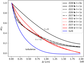
Figure 6. Autocorrelation function for the magnetic field alignment. Black curves show the correlation in the magnetic field direction, ACθ,B . The velocity direction autocorrelation, ACθ,v , is shown in red. As expected, correlations in the magnetic field are determined by correlations in the velocity for all but the most strongly magnetized simulations. In the most strongly magnetized case, the velocity is more correlated, and the field is less correlated than the velocity. The blue line shows ACθ,B for a simulation of driven turbulence to indicate an extreme case of disorder. The correlation in the field itself is intermediate between an ordered dipole and a fully turbulent field.
Download figure:
Standard image High-resolution imageFigure 6 also shows the B and v autocorrelations at t = 1.0 s for all runs. All four simulations begin with the same dipole field. As the simulation proceeds, the burning drives a number of instabilities, among them RT and Kelvin–Helmholtz, which cause fluctuation in the field direction due to flux freezing. This can be seen as a decrease in the autocorrelation. Three of the simulations have identical autocorrelation functions. These are shown as dashed, dotted, and dotted–dashed lines in black but are indistinguishable from each other. Only the most strongly magnetized run shows any deviation. That simulation (solid black and red lines) shows small differences in the magnetic correlation, with the magnetic field resisting some small amount of tangling. It additionally shows a substantial difference in the velocity correlation, with larger-scale flows being more active.
We can further quantify the tangling by defining the autocorrelation length,

which describes the length at which there is appreciable correlation. This quantity can be seen relative to the initial WD radius in Figure 7. This plot shows that the correlation length monotonically decreases with time as the field becomes more tangled, and this length is not particularly sensitive to our initial magnetic field.
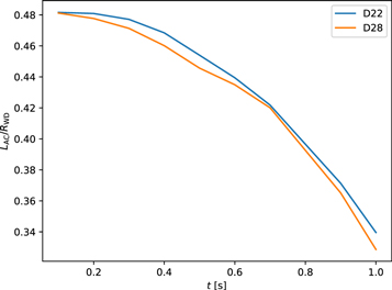
Figure 7. Autocorrelation length, defined by Equation (12), of the magnetic field as a function of time, in units of the initial WD radius, RWD. Initially, the magnetic field is correlated over half the star, but it decreases to a fraction of that. Improved resolution would likely cause this to decrease further.
Download figure:
Standard image High-resolution imageThe conclusion from this discussion is that the topology of the magnetic field is determined primarily by the burning front and not greatly influenced by the initial field. The topology of the magnetic field, as well as its strength, influences the rate at which positrons diffuse away from their place of origin. Larger correlation lengths allow positrons to travel further, while a more tangled field traps the positrons. As our initial conditions are heavily idealized, we cannot predict what values LAC will attain for a real SN Ia, but we have established that a burning SN cannot support a magnetic field topology as simple as a dipole.
Additionally, we are further justified in neglecting the back-reaction of the magnetic field on the flame during the stage 2 simulations. Since the strength of the field does not impact its topology, it also does not impact the burning front in an appreciable way, and we can neglect it for our purposes in stage 2. While there is a small effect of the field in the strongly magnetized run, it is unlikely to change our conclusions in a qualitative manner.
3.3. Burning
We show the difference in burned mass in Figure 8. From this, we see that the strongly magnetized case, D28, burns about 15% less nickel than the other three runs. For the initial drop before 0.1 s, the difference in burning rate is due to the initial excess of magnetic energy that decreases the central density somewhat. Beyond 0.1 s, the difference in burning rates is largely due to differences in the morphology of the interface. This can be seen by comparing the difference in burning rate (the slope of the bottom panel of Figure 8) and the difference in LAC in Figure 7.
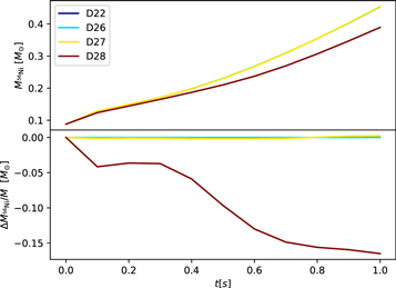
Figure 8. Nickel mass vs. time for all four simulations (top) and mass difference relative to D22. The three weakly magnetized simulations are nearly indistinguishable, but the strongly magnetized run shows a sustained reduction of the burning rate for the duration of the simulation.
Download figure:
Standard image High-resolution image3.4. Amplification
Figure 9 shows the magnetic energy versus time for each simulation. There is an initial drop as the field relaxes from our out-of-equilibrium initial conditions, and the field energy is converted in part to kinetic energy (see Figure 4). Since the burning is nearly identical, the difference in kinetic energy between the runs comes from the release of magnetic energy. To examine the subsequent evolution, we plot the change in total magnetic energy relative to t = 0.1 s, right after the initial conditions relax. The total magnetic energy for three of the runs continues to decrease, while D27, the second-strongest field, shows a slight increase.
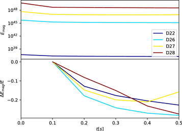
Figure 9. Magnetic energy vs. time for each of the runs (top). (Bottom) Relative magnetic energy change after the initial conditions relax. No evidence of field growth is seen except for a small increase in D27.
Download figure:
Standard image High-resolution image3.5. Spherical Symmetry
Even though there is a substantial magnetic field, the structures within the WD stay relatively spherically symmetric, on average, because the overall system stays in hydrostatic equilibrium dominated by the gravitation. Figure 10 shows the angle-averaged density versus radius at t = 0.6 s. The top panel shows the average density and the standard deviation from spherical,  . Error bars are shown on all plots but are smaller than the line width for a small radius. The deviation from spherical is most pronounced in the strongly magnetized run. The bottom panel of that figure shows the normalized standard deviation, σρ
/ρ. The peak σρ
is 8% for the most magnetized case. The few-percent deviation enjoyed by all simulations at r > 3 × 107cm is due to the boundary of the domain. Future work will employ a slightly larger domain to avoid this effect. The majority of the simulations are spherical to a fraction of a percent for the bulk of the evolution.
. Error bars are shown on all plots but are smaller than the line width for a small radius. The deviation from spherical is most pronounced in the strongly magnetized run. The bottom panel of that figure shows the normalized standard deviation, σρ
/ρ. The peak σρ
is 8% for the most magnetized case. The few-percent deviation enjoyed by all simulations at r > 3 × 107cm is due to the boundary of the domain. Future work will employ a slightly larger domain to avoid this effect. The majority of the simulations are spherical to a fraction of a percent for the bulk of the evolution.
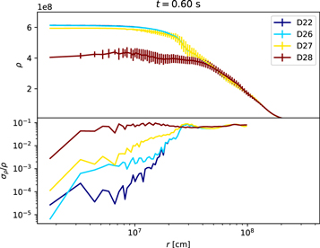
Figure 10. Density vs. radius at t = 0.6 s for each of our simulations. Error bars show the deviation from spherical. (Bottom) Standard deviation in the density. Errors in the strongly magnetized run are on the order of a few percent.
Download figure:
Standard image High-resolution image4. Stage 2 Evolution: Observable Consequences and Implications of Late-time Evolution
Based on the results described in the previous section, we will show the MHD effects discussed above based on the imprint on the late-time LCs (Milne et al. 2001; Penney & Hoeflich 2014) and NIR line profiles (Hoeflich et al. 2004; Penney & Hoeflich 2014; Diamond et al. 2015) in the framework of delayed-detonation models (Khokhlov 1989; Hoeflich & Khokhlov 1996).
In the stage 1 simulations, we studied the evolution of the morphology of the B-field based on the initial density structure and the adiabatic coefficient γ, consistent with the equation of state used in the explosion simulations of HYDRA, namely, the parameters of the spherical delayed-detonation model 23 of Hoeflich et al. (2017b). In stage 1, the size of B is a free parameter. This model starts with a WD originating from a main-sequence star of 7 M⊙ and solar metallicity Z0. The accretion rate from the donor star has been tuned to produce a thermonuclear runaway at a central density ρc
= 2 × 10⁹ g cm−3. In stage 2, we followed the deflagration phase during the distributed regime of burning and the subsequent detonation phase. The delayed-detonation transition has a transition density  . We triggered the delayed-detonation transition “by hand” because the mechanism(s) leading to the DDT have not been established. We choose this model because it can reproduce the observed curves, color–magnitude relation, and optical–to–mid-IR (MIR) spectra of a typical normal-bright SN Ia, namely, SN 2014J (Diamond et al. 2015; Telesco et al. 2015; Hoeflich et al. 2017b).
As in previous studies of the effects of B on positron and photon transport, we consider the nebular phase when the optical depth and density are both low, wherein forbidden atomic transitions dominate. The instant energy input from radiative decay of 56Co governs the bolometric luminosity. Moreover, during the late phase, the envelope is homologously expanding, so that the position and velocity of a mass element are related as r(m, t) ∝ ∣ v (m, x, y, z)∣ × t = v(m) × t. Only the radial component of v remains. The line profile of unblended features is a result of the Doppler shift of the mass element m and the energy deposition.
The HYDRA code employs full 3D transport and hydrodynamics, including the time dependence (see Appendix B). However, the results in the nebular phase are dominated by forbidden lines in a mostly optically thin envelope. The solution of the statistical equations is dominated by the branching ratio between atomic energy levels j and i, here determined predominately by the Einstein values Aji (Motohara et al. 2006; Penney & Hoeflich 2014; Diamond et al. 2015; Telesco et al. 2015), and the radiation transport is close to the optically thin limit, leading to the stability of the results.
As discussed below, the lower limits given below for the size of the B-field derived from spherical LCs is not affected by 56Niplumes or instabilities. This is because mixing out of 56Ni would increase the escape probability of positrons and γ-rays (see Figure 11), which would increase the estimate for B, but our lower limits will still be valid. The lower limits correspond to average surface fields assuming a magnetic topology identical to D22, for which our simulations of stage 1 show small deviations from sphericity. Even using the slightly less spherical model D28 results in only a slightly higher field estimate; see Figure 11.
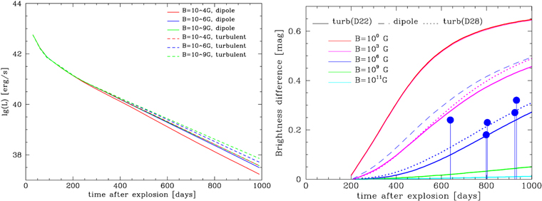
Figure 11. The LCs. Shown is the influence of the magnetic field morphology on LCs for large-scale undisturbed dipoles and the field structure produced by the turbulent morphology produced by RT instabilities starting from an initial dipole field in the WD for models D22 (solid lines) and D28 (dotted lines). The left panel shows the LC for a fixed dipole that does not evolve (solid) and the turbulent field taken from D22. The right panel shows the evolution of the deviation with respect to our fiducial LC to show the differences between D22 (solid lines), D28 (dotted lines), and the fixed dipole (dashed line). As a background explosion model, we use the delayed-detonation model 23 with parameters from Hoeflich et al. (2017b) for a normal-bright SN Ia and imprint the B-morphology with surface fields up to 1013 G, which causes local trapping of positrons (see Table 2). We show the corresponding bolometric LCs (left) and the difference (right) relative to the case of full local trapping. Note that a field size of 1011 G is already close to local trapping even at 1000 days. The details of the morphology of a turbulent field have a minor impact (D22 vs. D28), but large-scale ordered fields allow for a significantly larger fraction of positrons to escape. As a result, the solution for the dipole field of 103 G is almost indistinguishable from the field-free case, and its field of 106 G produces an escape similar to a turbulent field but some 3 orders of magnitude smaller. In addition, we give the loci of the upper limits for SN 2012cg, SN 2003hv, SN 2014J, SN 1992A, and SN 2011fe (blue dots from left to right). All SNe are consistent with complete trapping of positrons. Note that an assumed uncertainty of 0.15–0.2m for a bolometric LC implies the need for observations beyond ≈500 days. As discussed in the text, all LC observations follow the case of local trapping of positrons (green dashed). At about 700–1000 days, additional radioactive heating places their locus above the full trapping case, limiting the use of LCs to times before day 1000. For the estimates of the lower limit in B (Table 3), we assume data starting beyond ≈250 days using Lbol for a normal-bright SN Ia (Paper II). Note that beyond day 300, more than 95% of the energy input is from positrons (see text).
Download figure:
Standard image High-resolution imageNote that we make the case that asphericities in ρ for the highest B-fields may not survive further evolution based on pure 3D hydrosimulations (Khokhlov 2001; Gamezo et al. 2003b, 2005; Röpke et al. 2012). However, this has not been shown in this work.
We use the morphology of the magnetic field for model D22 at 0.6 s and scale the average surface magnetic field between 1 and 1013 G. For a grid of magnetic fields of 100,1,3,4,6,9,11,13 G, the positron, γ, and photon transport problem have been simulated at 100, 150, 200, 300, 400, 500, 750, and 1000 days. For verification of our main conclusion, we have used the imprint of the highest magnetic field hydromodel (D28) with 1013 G. We note that large-scale asymmetries in the density and chemical structure will affect the line profiles, as shown in previous simulations for 3D turbulent or off-center delayed-detonation models (Höflich 2002; Höflich et al. 2006; Motohara et al. 2006).
4.1. Magnetic Field Effects on Late-time LCs
The results can be well understood within the following framework. The B-fields are frozen in the comoving frame because of the plasma. Positrons are scattered and lose energy by collisions with electrons until the energy is below the binding energy. At this point, they are annihilated. For details, see Appendix B.
To first order, the SN envelope is freely expanding. The density drops with time t as 1/t3, and the length scale increase ∝ t. As a result, the mean free path of positrons relative to the expanding envelope increases like t2 before annihilation.
In the presence of B-fields, positrons gyro around the field lines with the Larmor radius. If the structures in the field morphology are smaller than the Larmor radius, the positrons are trapped. Because structures grow linearly with t but the Larmor radius increases like t2, positrons will eventually propagate beyond these structures (see Table 2).
Table 2. Maximum Larmor Radius as a Fraction of the Size of the SN Envelope at Various Times and Initial Surface Field Strengths
| Field/Time | 100 days | 300 days | 500 days | 750 days | 1000 days |
|---|---|---|---|---|---|
| 103 G | 1.9 | 5.7 | 9.6 | 14.4 | 19.1 |
| 104 G | .19 | .57 | .96 | 1.4 | 1.9 |
| 106 G | .001 | .005 | .009 | 0.013 | 0.02 |
| 109 G | 1.9E-6 | 5.E-6 | 9.E-6 | 1.3E-5 | 2.E-5 |
| 1013 G | 5.E-11 | 1.2E-10 | 2.E-10 | 3.3E-10 | 5.E-10 |
Note. During the nebular phase, the expansion is homologous with the distance of a mass element r(m) ∝ v(m) × t. Here v(m) and r(m) are equivalent measures of the envelope structure. However, v(m) corresponds to a spectral Doppler width observable in spectral line profiles. Here the size of the envelope is defined by the layer expanding with a velocity of 40,000 km s−1. In our simulations, the typical size of the B-field structure is produced by RT instabilities (≈500 ... 1000 km s−1 in velocity units or 1 ... 2 × 10⁻² in units of the envelope size).
Download table as: ASCIITypeset image
Theoretical bolometric LCs, Lbol, and the difference in magnitudes in V, a proxy for Lbol, are shown in Figure 11 for magnetic fields between 0 and 109...11 G. The zero-field case is identical to the B = 103...4 G dipole field, and the total local trapping case is virtually identical to the B ≥ 109 G turbulent cases for all times. The early LCs are identical because γ-ray transport does not depend on B, and the free mean path of the positrons is small. At about 220 days, the energy input from positrons equals that from γ-rays. The LCs with different magnetic fields start to diverge after about day 300 when the mean free path of some of the positrons becomes large compared to the envelope. Small-scale structures and high B-fields trap positrons for longer than low-B and/or large-scale dipoles. The luminosity for the simulation with B = 109 G and a turbulent field closely follows the energy input from the decay of 56Co even at day 1000, which shows that the positrons are not able to escape the region of their birth. The difference (Figure 11, right) between the models may be in excess of 0.5m , which should be easily measurable given current observational accuracy. We examine observed LCs in the next section.
4.1.1. Magnetic Field Strengths in Known SNe
We want to combine the results of Figure 11 with observations. Using our simulations (Figure 11, right panel) and applying the deviation of the observed range in time, a given SN Ia provides estimates for the size of the B-field. The detailed reconstruction of Lbol is beyond the scope of this paper; thus, we refer to the Lbol (or V as proxy) given in the literature.
We use the radioactive tail of the fiducial LC that keeps the positrons local and compare it to simulations with a variety of magnetic field strengths and topologies. We then compare these differentials to observed SNe to determine the lower limits of their field strengths. This can be seen in the right panel of Figure 11, which shows the deviations from full trapping for each of our model simulations, as well as the upper limits on the deviation (and thus lower limits on the field strength) for several known SNe.
Relatively few late-time LCs are available. Milne et al. (2001) suggested some indication for positron escape by day ≈170, but this was based on strictly radial B-fields in the models and neglected NIR and MIR emission. Multiband LCs are required to reconstruct Lbol with sufficient accuracy to include the redistribution of photons to the NIR and MIR within an accuracy of ≈0.15m (Stritzinger et al. 2002; Sollerman et al. 2004; Gall et al. 2018). If NIR data are not available, we use the redistribution functions from our models for normal-bright and transitional SNe (Hoeflich et al. 2017b; Gall et al. 2018) and redistribution functions based on observations of SN 2014J (Telesco et al. 2015). We use the intrinsic uncertainty from the scatter in the measurements. For Lbol, based on the references above, we add to the measurement error in the LC points an additional error of 0.15m to the reconstruction of Lbol if IR observations are available and 0.2m if they are not.
None of the observations fall below the LC expected from the decay of 56Co, indicating full local trapping by magnetic structures. To determine the lower limits of the initial B, we use the curves of Figure 11 and determine the maximum deviation from the theoretical curves that are consistent with the decay of 56Co. Obviously, these limits depend on the coverage of the late-time LCs and error bars. Observed LCs include SN 1992A (≈950 days; Cappellaro et al. 1997), SN 2003hv (≈700 days; Graur et al. 2016), SN 2011fe (≈930 days; Kerzendorf et al. 2014), and SN 2012cg (≈1060 days; Graur et al. 2016). The SN 2014J has been observed even beyond 1200 days, showing the onset of radioactive decay of elements besides 56Co. This flattens the LC by about day 800, indicating the onset of 57Co decay as the dominant energy source (Yang et al. 2018). The SN 2014J was found to be consistent with the decay of 56Co and with no signature for positron escape or an IR catastrophe predicted by Fransson & Sonneborn (1994). Similarly, SN 2003hv and SN 2011fe are observed after the onset of 57Co heating or interaction, and neither LC drops below the 56Co or 57Co line, giving evidence for full positron trapping. Results for the lower limit are summarized in Table 3. This shows that high B-fields are common, well in excess of typical fields observed in WDs (see Section 1). Note that, in the presence of a deflagration phase in MCh-mass explosions, large-scale dipole fields will be transformed into small-scale turbulent fields. Alternative explosion scenarios involve pure detonation burning. For these, the dipole field morphology may remain (see next section), leading to even larger lower limits for the initial B-field.
Table 3. Lower Limits for Magnetic Field Strengths from Known SNe
| Name | t (days) | Bturb | Bdipole | Reference |
|---|---|---|---|---|
| SN 1992A | 926 | 105.5 | 108.5 | Cappellaro et al. (1997) |
| SN 2003hv | 800 | 106 | 109 | Leloudas et al. (2009) |
| SN 2011fe | 930 | 105 | 108 | Kerzendorf et al. (2014) |
| SN 2012cg | 640 | 104 | 107 | Graur et al. (2016) |
| SN 2014J | 800 | 105.5 | 108.5 | Yang et al. (2018) |
Note. The dates correspond to the last data point observed. The loci in Figure 11 are the last data points before additional energy sources contribute to the LC.
Download table as: ASCIITypeset image
4.1.2. Magnetic Field Effects on Line Profiles
The LCs are a powerful tool, but their application is limited as tools to constrain B because LCs tend to flatten after 700–1000 days. Line profiles and their variations as a function of time were suggested as an alternative diagnostic tool in Paper II.
In particular, [Fe ii] at 1.644 μm has been identified as having only minor blends in the line wing (Hoeflich et al. 2004; Motohara et al. 2006; Penney & Hoeflich 2014; Diamond et al. 2015, 2018). All other strong features at shorter wavelengths are blends produced by multiple transitions. Alternatively to the NIR [Fe ii], the MIR has been demonstrated as a source for unblended [Co ii] and [Fe ii] lines by Telesco et al. (2015), but it is likely that those are beyond reach but for the upcoming James Webb Space Telescope (JWST). Here we want to discuss the NIR [Fe ii] (Figures 12 and 13).
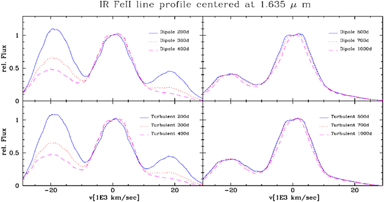
Figure 12. Angle-averaged line profiles for the “almost” unblended feature produced by the forbidden [Fe ii] at 1.644 μm for an initial average surface field of 106 G. The time evolution for the dipole (top row) and turbulent (bottom row) fields shows little evolution before 400 days (left column) due to the local trapping of positrons. For the dipole and turbulent fields, the profiles start to change after about 400 and 700 days, respectively (right column). A total of ≈100,000 line profiles have been calculated (magnetic field*morphology*phases*θ and ϕ direction ≈105), are available on request, and will be part of a database for different explosion models.
Download figure:
Standard image High-resolution image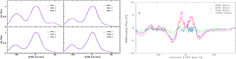
Figure 13. Same as Figure 12 but for [Fe ii] line profiles for the dipole field as seen from 0o (1), 30o (2), or the pole (3) at given times (left panel). The late-time differences in the profiles (∼1000 ... 15,000 km s−1), although not prominent on this plot, are significant, given a typical spectroscopy resolution of ≈100 km s−1. In addition, and as proof of concept, differences between NIR spectra between the dipole seen equator-on and the turbulent field are shown on the right, with spectra normalized to the average spectra at day 500. Dipole fields produce a characteristic large-scale pattern and signals of about ±5% between ±15,000 km s−1. For turbulent fields, variations correspond to the mass of the individual plumes and show up as wiggles on the 1% level. Note that spectroscopy allows precise measurements of Doppler shifts, but flux differences on the 1% level will be reserved for observations with the upcoming JWST. For details, see text.
Download figure:
Standard image High-resolution imageThe profile is a measure of the distribution of the energy input by positrons convolved with the Fe abundance. The line profiles are more sensitive to positron transport effects because changes do not require the escape of positrons, but nonlocality of the positron decay is sufficient (Penney & Hoeflich 2014). It provides information about the distribution and possible offset of radioactive 56Ni → 56Co → 56Fe and, at ultralate times, other decay channels of radioactive isotopes of the iron group (Hoeflich et al. 2017c). For the time series, we use the small variation in the line profile as an indicator for B-fields.
Inherently, the effects of B can be detected earlier, namely by day 400 ... 500 and, in principle, without restrictions to late times well beyond 1000 days. However, optical depth effects, namely, the underlying optically thick photosphere and nonlocal energy input by γ-rays for iron close to the center, lead to a change of the forbidden [Fe ii] line profile at 1.644 μm, rather than revealing positron transport effects (Figure 12, left). However, the line profile hardly changes between 300 and 400 days. This requires a reference point for the spectra later than 300 days. Note that the two features to the right and left correspond to [Co iii] and [Fe ii] blends and variations that are caused by the nuclear decay with time (Höflich et al. 2004). In practice, one problem is related to the costs of obtaining NIR spectra of high quality and the need for a time series, which limits the number of objects to a few (see Section 1).
As an example and for a field of B = 106 G, the evolution of the profiles is shown as a function of time and orientation in Figure 12. For both turbulent and dipole fields, the [Fe ii] profiles remain almost unchanged between 300 and 400 days after the explosion, because γ-rays do not contribute substantially to the energy input, and positrons annihilate locally. After about day 500, the profile becomes increasingly narrow because positrons at the outer, high-velocity, low-density regions of the 56Ni distribution become nonlocal; that is, they move away from their generation region and excite other lines and elements within the envelope.
One fundamental problem in deciphering the distribution of the radioactive 56Ni is that a large-scale B-field, e.g., a dipole, causes strong directional dependence when a particular SN Ia is observed. The dependence of the line profile on viewing angle can be seen in Figure 13. In our example of a large-scale dipole, positrons can travel almost unhindered along the axis of symmetry, the polar direction; thus, the effective mean free path has a small dependence on B, as opposed to the highly inhibited travel along the equator. The changes between 500 and 750 days and 500–1000 days are comparable when seen from the equator and pole, respectively. The rate of change does depend on both the size of B and the direction of the observer.
For the turbulent field, the profiles show little directional dependence. Fluctuations are restricted to the scale of the convective eddies, which, in principle, may be recovered by high signal-to-noise ratio observations with a resolution of the characteristic eddy velocities, i.e., 1000 km s−1. We note that the evolution of the profile, e.g., the mean half-width, is nonmonotonic (Diamond et al. 2015) and thus requires at least three observations to recover.
One of the main results of our MHD simulations is that for a wide range of B, the morphology is given by a turbulent field even for a large-scale initial dipole during the deflagration phase. This does not rule out large dipole fields in, e.g., pure detonation scenarios.
5. Final Discussion and Conclusions
We have studied the effects of magnetic fields on deflagration fronts and late-time spectra in SNe Ia. We find that small-scale magnetic fields develop as a result of the motions of the burning front, and that observations put the magnitude of the magnetic fields into a regime that may be both relevant and larger than commonly observed in single WDs.
We employed initial maximum fields between B = 107 and 1015 G in the framework of delayed-detonation models. We examine their imprint on LCs and spectral properties during the nebular phase. Using our model LCs, we estimate lower limits of 106 G for several published SNe. We also find that RT instabilities develop early, even in the presence of magnetic fields that, energetically, should suppress the instability.
The two weakly magnetized runs, D22 and D26, are almost entirely identical in their evolution in all measurable quantities. This is unsurprising, as the magnetic pressure is several orders of magnitude lower than the gas pressure at all radii for both of these simulations. This also shows that we are not troubled by systematic variations other than those caused by the magnetic field. Tangling develops early (0.5 s) in all runs. There is slightly less tangling in the strongly magnetized simulations, as well as more pronounced RT instability. The strong initial field in D28 supports large-scale flow structures, which results in a faster increase in rising plumes, as well as reduced burning surface area. This can explain why D28 has 15% less 56Ni versus lower B, as in Paper (I).
We do not see any evidence of magnetic field amplification in these simulations, as expected from previous studies (Paper I), though this does not rule out amplification with other initial magnetic topologies.
We started our simulations with a burned central region that, in size, corresponds to about 1–2 s after the thermonuclear runaway in models of central ignition. This is the onset of RT in models with central ignition (Khokhlov 2000; Gamezo et al. 2005). In off-center and multispot ignitions, the development of RT instabilities is faster (Hillebrandt et al. 2013). Though we do not follow the deflagration front during the regime of distributed burning, the tangling cannot be expected to decrease. Rather, in the absence of a large-scale flow to order the field, it can only be expected to increase during the regime of distributed and detonation burning. We show that the density distribution remains spherical to within <1% in the most strongly magnetized case. This is due to the dominance of pressure equilibrium and gravity, a result found previously by hydrosimulations for quasi-nuclear statistical equilibrium of explosive oxygen-burning regions (Gamezo et al. 2003b, 2005).
In Section 4, LCs between 500 and 1000 days are shown to be able to constrain the strength of the magnetic field, and we use these model LCs to estimate magnetic field strengths of >106 G from several observed SNe. Line profiles, or rather their lack of time evolution, can be used to constrain B starting at about day 300. For magnetic fields larger than 106 G, positrons are trapped within the magnetic field up to about day 500, which presents the current limit from observations. However, changes in the profiles or the width of the line can be used to determine the magnetic field strength for larger initial fields because, in principle, the method of using specific line profiles can be applied to even later phases than LCs. Currently, only a few SNe Ia with sufficiently late-time NIR spectra or optical and IR LCs are available. A larger number is needed to confirm whether high B-fields are generally present. Figure 11 may provide a tool to get a first-order estimate of B-fields for future observations.
As mentioned in the Introduction, an obvious question is the origin of such a field. The magnetic decay timescale of 109 K plasma is 109 yr, so it is natural for such a plasma to support magnetic fields, and the question is identifying its source. Within dynamo theory (e.g., Brandenburg & Subramanian 2005), there are several mechanisms to amplify the field up to the saturation strength of ∼1014 G (Chandrasekhar 1956; Chandrasekhar & Prendergast 1956; Mestel 1956; Paper I), and the nature of the amplification mechanism will be imprinted in the magnetic field structures. This may happen at several points during the evolution of the WD. In the Chandrasekhar-mass, MCh, explosions considered here, a WD close to equilibrium begins to burn as a result of compressional heating, which in turn results from accretion from a companion. This leads to subsonic deflagration, which then transitions to supersonic detonation. The correlation length of the flow during each phase will set the correlation length of the magnetic field, which in turn impacts the escape of positrons. During the accretion phase, the dominant length scale is the radius of the WD. During the late-stage run-up to the deflagration, the so-called “smoldering phase” (Hoeflich & Stein 2002; Zingale et al. 2011), the dominant length scale is the pressure scale height of the star. During the supersonic explosion, the scale is set by the sound-crossing timescale because the flame propagates as a weak detonation. Our results show that amplification during the deflagration phase is unlikely. Hydrodynamical simulations (Gamezo et al. 2003b; Röpke et al. 2012) have shown that the instabilities that could give rise to a dynamo are frozen out during the expansion phase of the WD. This leaves the accretion or smoldering phases as the likely candidates for magnetic field amplification in WDs.
This leads us to the discussion of these results in the framework of alternative explosion scenarios. Likely, a combination of different explosion scenarios is realized in nature. The quest for the predominant mechanism is still under debate, with time changing the favorites. This is not too surprising, because several properties of the WD, namely its structure, the explosion, the light curve, and the spectra, are determined by nuclear physics and processes (Hoeflich et al. 2013). This phenomenon is also known as “stellar amnesia.” The mass ranges for normal-bright SNe Ia and HeDs are ≈1.0 ... 1.1 M⊙ (Pakmor et al. 2012; Shen et al. 2018) and 1.28–1.38 M⊙ for MCh-mass explosions (Hoeflich et al. 1998; Diamond et al. 2015). For a longer review of explosion scenarios, details and further references are given in the Introduction, Hoeflich (2017), and, for individual aspects of the explosion, the chapter titled “Physics of Thermonuclear Supernovae” in Alsabti & Murdin (2017). During dynamical merging of two WDs (e.g., Pakmor et al. 2011), high B-fields are likely to develop, depending on the details of the dynamical merging process. However, no significant B-field amplification can be expected for He-triggered explosions because they explode promptly on timescales of a second triggered by a supersonic shock, and the progenitor evolution involves two WDs without a deflagration or smoldering phase. However, a large-scale dipole field may develop during the accretion phase, similar to the massive He/Co systems described in Pakmor et al. (2021).
Finally, we would like to discuss some limitations beyond those just mentioned that will be overcome in future. Our study is not a full end-to-end simulation of the explosion of a WD. Rather, we studied the change of the morphology of an initial magnetic field during the regime of nondistributed burning and the observable consequences. The initial condition of the 3D simulation starts from a WD structure but a rather advanced stage of burning to shorten the time until the RT instabilities can develop. We do not follow the ignition process. At the end of the 3D simulations, further evolution is followed by spherically symmetric hydrodynamics without magnetohydrodynamical effects.
For our analysis of the NIR spectra and LCs, we have considered a specific explosion model and realization. A more comprehensive study including spectra at 750 days and beyond is underway, encompassing transitional and subluminous SNe Ia and alternative explosion scenarios.
The NIR spectra of SN 2004du, 2005df, and 2014J and the optical LCs of five SNe Ia discussed in this paper suggest that B-fields in excess of 104...6 G are common. One obvious limitation is the lack of observations for a larger sample. With the upcoming JWST, unblended line profiles of Co in the MIR will become available (e.g., Gerardy et al. 2007; Telesco et al. 2015), and WFIRST will cover the LC evolution of many local SNe Ia “by chance.”
We thank the referee for carefully reading the manuscript and many helpful suggestions. We acknowledge the support of National Science Foundation (NSF) grant AST-1715133, including the salary for a postdoc. Most of the development and simulations have been done on the Local Cluster of the FSU astro-group, including the data storage. This work used the Extreme Science and Engineering Discovery Environment (XSEDE, https://www.tacc.utexas.edu; Towns et al. 2014), which is supported by NSF grant ACI-1548562, under XSEDE allocation TG-AST140008.
Software: Enzo (Bryan et al. 2014), HYDRA (Hoeflich 1990; Hoeflich et al. 1993; Höflich 2003a, 2003b, 2009; Penney & Hoeflich 2014; Hoeflich et al. 2017a). Plotting and analysis was done using yt (Turk et al. 2011), matplotlib (Hunter 2007), and numpy (Van Der Walt et al. 2011).
Appendix A: Mass and Molar Fractions and Burning Operator
Here we define the mass and molar fractions in terms of other quantities and provide some identities. First, note that in a fuel/product mixture, the partial mass densities add up to the total mass density:

Let the respective molar masses be  and
and  . The mass, molar, and burned fractions, X, Y, and f, are defined as follows:




For the burned fraction, 0 ≤ f ≤ 1 always holds, whereas f = 0 corresponds to pure fuel and f = 1 to pure product. The two mass fractions obey Xfuel + Xprod ≡ 1.
Equation (A1) allows for a code to keep track of one partial density variable in addition to the total mass density. In our case, we had chosen the product density. The burning operator, Equation (8), is evaluated at the end of the time cycle. Below are the identities necessary to go back and forth between the relevant quantities:


All of our MHD simulations assume the product to be 56Ni, as well as a 12C:16O molar ratio of 50:50 for the fuel mixture. This corresponds to  . Note that ρprod is a tracer field not entering the MHD equations.
Appendix B: Radiation Hydrodynamics with HYDRA
Our HYDRA code consists of physics-based modules to provide a solution for the nuclear networks and the statistical equations needed to determine the atomic-level population, equations of state, opacities, and hydro and radiation problems. The individual modules are explicitly coupled (Figure 14). Consistency between the solutions is achieved iteratively by perturbation methods, a combination of accelerate lambda acceleration plus equivalent two-level approach (ALI2) net cooling and heating rates for radiative coupling terms (Höflich 2003a, 2009) and excitation and ionization by hard radiation and particles. Different modules are employed during different stages of the simulation. Below, we will give the basic equations with references to the methods actually used in this paper, using standard notation as in Mihalas & Weibel Mihalas (1984) wherever possible. Several of the modules are formally used as part of HYDRA but do not affect the results in this paper, as discussed in the main text.
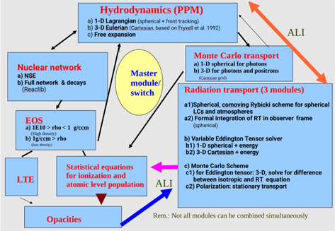
Figure 14. Block diagram of our numerical scheme to solve radiation hydrodynamical problems, including detailed equation-of-state, nuclear, and atomic networks.
Download figure:
Standard image High-resolution imageHydrodynamics. The structure of the expanding envelopes are obtained by using one of three modules: (a) assuming free expansion, or by solving the nonrelativistic hydro equations in (b) the Lagrangian frame for spherical geometry including a front tracking scheme to resolve shock fronts (Fryxell 2001), or (c) the Eulerian scheme for full 3D using Cartesian coordinates based on PROMETHEUS (Fryxell et al. 1991). In this paper, we use module (b) for the early evolution until ≈day 10 and module (a) afterward. The hydro modules use an explicit piecewise parabolic method (PPM) by Colella & Woodward (1984) to solve the compressible reactive flow equations with variable adiabatic gradients based on low- and high-density equations of state (see below). The PPM is implemented as a step followed by separate remaps of the thermal and kinetic energy to avoid numerical generation of spurious pressure disturbances during propagation of reaction fronts (flames and detonations).
Deflagration fronts. For spherical geometry, the deflagration speed in mass coordinates is given by

with vcond being the conduction speed, with the Atwood number αT
= (α − 1)/(α + 1) and α = ρ+(rburn)/ρ−(rburn), rburn being the distance of the front from the center and ρ+, ρ− the density jump across the front, and Lf
is the characteristic length scale for the freeze-out of the turbulence. The main effect of the expansion is the freeze-out of the turbulence on scales Lf
, where the turbulent velocity vt
due to RT instabilities is comparable to the differential expansion velocities. For these flows,  , where vexp is the expansion velocity at time t. The C1 has been calibrated (Domínguez & Hoeflich 2000) based on 3D hydrodynamical simulations (Khokhlov et al. 1997; Gamezo et al. 2003b). Here we did use C1 = 0.2. In other works, where we employ 3D hydro, we use the burning operator given in Equations (8) and (9).
High-density equation-of-state and nuclear reactions. The equation of state is for a partially degenerate and partially relativistic Bose and Fermi gas plus interactions due to the effects of Coulomb corrections, quantum relativistic effects on the electron component, and electron–positron pair production (Chandrasekhar 1931; Van Horn 1969; Slattery et al. 1982; Giordano et al. 1984; Nomoto & Thielemann 1984; Hoeflich 2006). Electron screenings are taken from Graboske et al. (1973) in the weak, intermediate, and intermediate-strong regimes and from Itoh et al. (1979) in the strong regime.
Nuclear reactions are used in the high-density regime and temperatures above 5 × 10⁵ K. A network is used with rates including weak, strong, and electromagnetic reactions. It is based on the implementation by Thielemann et al. (1994a, 1994b) but with modified matrix solvers. For isotope i, the change of the abundance ratio per nucleon Yi is given by

The first term on the right-hand side includes single-particle processes, with decays, photodisintegrations, electron and positron captures, and neutrino-induced reactions with λj
being the rate per particle j. The second term includes two particle reactions for particle densities nj
and nk
and mass density ρ, with NA
being Avogadro’s number and δjk
being the Kronecker delta. Here 〈σ
v〉j;k
is the nuclear cross section convolved by the velocity of the particles j and k in the plasma. Here Ni
j
and  are the number of particles j and k created or destroyed in the process, and O(3) includes terms due to multiparticle reactions. Here we use 218 isotopes, but the solver has been used for up to 2438 isotopes. For temperatures larger than 6.5 × 10⁹ K, we assume nuclear statistical equilibrium mediated by strong and photon-induced reactions, with only terms due to weak reactions remaining in the rate equations. For 〈σ
v〉i;k
, the Boltzman distribution is assumed for the velocity v of the isotopes in the plasma. The individual rates between isotopes are fitted by expansions in ρ and T with factors tabulated in the reaction network library REACLIB and modified weak reactions. Updated cross sections are as published in Cyburt et al. (2010). For more details, see, e.g., Thielemann et al. (1994a) and Langanke (2004).
are the number of particles j and k created or destroyed in the process, and O(3) includes terms due to multiparticle reactions. Here we use 218 isotopes, but the solver has been used for up to 2438 isotopes. For temperatures larger than 6.5 × 10⁹ K, we assume nuclear statistical equilibrium mediated by strong and photon-induced reactions, with only terms due to weak reactions remaining in the rate equations. For 〈σ
v〉i;k
, the Boltzman distribution is assumed for the velocity v of the isotopes in the plasma. The individual rates between isotopes are fitted by expansions in ρ and T with factors tabulated in the reaction network library REACLIB and modified weak reactions. Updated cross sections are as published in Cyburt et al. (2010). For more details, see, e.g., Thielemann et al. (1994a) and Langanke (2004).
Low-density equation of state, opacities, and source functions. The data for the atomic levels and line transitions are taken from the compilation of Kurucz & Bell (1995), Seaton (2005), and Hoof (2010), supplemented by additional forbidden lines from Diamond et al. (2015). For the atomic models, we reduce the number of energy levels by use of level merging/superlevels, with the assumption that coupling between the merged levels is in thermodynamical equilibrium. This implies full frequency redistribution of individual transitions (see below). For the radiation transport, Voigt functions (Hui 1978) are assumed for the individual line profiles in the comoving frame. For Monte Carlo transport, we assume the narrow line limit (Sobolev 1957; Adams et al. 1971; Castor 2004) and take into account the probability for absorption along the way by lines of higher frequency, similar to the formulation by Karp et al. (1977) and the narrow line limit (Sobolev 1957; Hummer & Rybicki 1992; Höflich2003a). The module for molecular kinetics uses rates from Sharpton et al. (1970), Sharp (1988), Petuchowski & Dwek (1989), Lepp et al. (1990), Hashimoto et al. (1995), Gerardy et al. (2007), and Rho et al. (2021). In addition, the time-dependent formation of dust for carbonates, silicates, and iron crystals has been implemented as a kinetic gas theory based on the codes for dust formation (Dominik 1992; Dominik & Tielens 1997; Dominik 2009).
We solve the full set of statistical equations to determine the population density of atomic states, ni , where i is shorthand for the excitation state i out of js excitation states for the ionization state k of element el. The time-dependent level populations are given by the el × k × j equations,

Here the rate, Pij
, is the sum of the radiative, Rij
, and collisional, Cij
, processes;  stands for all transitions from all bound levels of higher ionization states.
The nonthermal excitation by hard γ-rays and electrons is added into the radiative rates R with fractions according to the individual level densities. Timescales in δ
ni
/δ
t are dominated by the slow bound–free transitions; therefore, only their time dependence is taken into account. Thus, the time-dependent solution can be obtained from the stationary solution  by solving an inhomogeneous ordinary differential equation analytically or as a simple system of linear equations (Hoeflich 1995a) of the form

The radiative rates between a lower- and an upper-level i and j, respectively, are given by
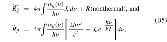
where  and R(nonthermal) are the energy input by hard radiation and nonthermal electrons, Jν
is the first momentum of the radiation field, αij
is the cross section, and an asterisk denotes values for thermodynamical equilibrium.
and R(nonthermal) are the energy input by hard radiation and nonthermal electrons, Jν
is the first momentum of the radiation field, αij
is the cross section, and an asterisk denotes values for thermodynamical equilibrium.
The equation of particle and charge conservation can be written in the following form:
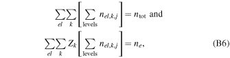
where el, k, and level are the sums over the element el, ionization state k, and all excitation levels for a particular ion, and Zk is the charge of the ion. The electron and total densities are given by ne and ntot, respectively. Complete redistribution over each individual line both in frequency and in angle is assumed in the comoving frame. Complete redistribution also implies that the relative populations within the sublevels or merged levels are described by a Maxwell–Boltzmann distribution.
The formal total source function Sν , emissivity η, opacity χ, and frequency redistribution function ψ are related by

with
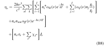
and
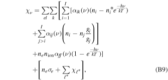
with α being the cross sections for bound–bound, bound–free, and free–free transitions. Here  are the opacities of those weak scattering lines not treated in NLTE.
Line redistribution functions. For the source function of low-energy photons, complete redistribution is assumed in general for each individual bound–bound transition. However, due to the large number of lines, they will overlap even in the comoving frame due to their natural line width, which results in a frequency redistribution in the case of radiation transport in spherical geometry. 4 The redistribution function ψν is evaluated numerically by weighting the neighboring frequencies with the overlap of a specific transition so that the frequency integral over Sν is conserved (Adams et al. 1971; Hummer & Rybicki 1992; Rappaport et al. 1994; Hoeflich 1995a). 5
Coupling of radiation transport, statistical, and hydro equations. We use the well-established method of accelerated lambda iteration (e.g., Cannon 1973; Scharmer 1984; Hillier 1990; Hoeflich 1990; Hubeny & Lanz 1992). We employ several concepts to improve the stability and convergence rate/control, including the concept of leading elements, the use of net rates, level locking, reconstruction of global photon redistribution functions, the equivalent two-level approach (Athay 1972; Avrett & Loeser 1988; Hoeflich 1995a), and predictor–corrector methods.
Radiation transport for low-energy photons. For the time-dependent transport, we use variable Eddington tensor solvers, which are implicit in time (Mihalas & Weibel Mihalas 1984; Stone et al. 1992; Höflich 2003a; Castor 2007, 2009; Höflich 2009), 6 and stationary solutions of the transport for the closures.
For spherical geometry, we solve the following equations:

and
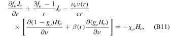
where β and the Eddington factors are defined in the usual way,

Here Jν , Hν , Kν , and Nν are the first four moments of the intensity. The fourth moment is needed as a closure relation of the system. The Eddington factors fν and gν are obtained from solutions for the stationary case by integration along rays in a Rybicki-like scheme for nonrelativistic and relativistic velocity fields including advection terms (Mihalas et al. 1975, 1976a,1976b; MKH methods). Note that the Eddington factors include the frequency redistribution function ψ. Time-independent Eddington factors are assumed during each time step.
For the 3D case, the variable Eddington tensor method is used, which is accurate to the order of O(u/v), and we neglect acceleration terms (Buchler 1979, 1983; Stone et al. 1992; Höflich 2009; Hubeny & Mihalas 2014). The system of equations is given by

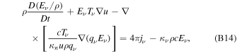
with the tensor T and, following Auer (1971), the variable qν as defined by


and
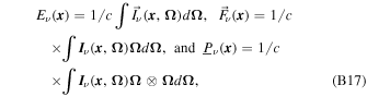
where the integrals over ν denote the corresponding radiative components in the hydro equations. For spherical geometry, the pressure is taken as the diagonal elements of  . For 3D, the advection frequency redistribution terms enter via the Monte Carlo solution. For some tests of 3D versus spherical solutions, see Hoeflich (2002). Again, we use stationary transport for the closure relation and test the result against the spherical transport module. Monte Carlo methods are used, including advection and aberration for the closure relation of low-energy photons for flux and polarization spectra, and similar to hard γ-ray and positron transport (Hoeflich 1991; Hoeflich et al. 1992; Hoeflich 1995b; Penney & Hoeflich 2014).
The γ-ray and positron transport. The γ-ray transport is computed in multiple dimensions using a Monte Carlo method (Hoeflich et al. 1992; Hoeflich 2003a) including relativistic effects and a consistent treatment of continuum and line opacities. Interactions are calculated in the local rest frame by transformation between observer and comoving frame. Photon and positron packages may persist until the next hydro time step. If the photon/positron travel time exceeds the time step, they are fed to the next time step. This persists until they are scattered down to low energies or X-rays or escape the computational domain. Each package keeps a time tracer that monitors its travel time.
The interaction processes allowed are Compton scattering according to the full angle-dependent Klein–Nishina formula, pair production, and bound–free transitions (Ambwani & Sutherland 1988), and interaction processes catalogued in the NIST XCOM database (Berger et al. 1998).
B.1. Positron Creation and Cross Sections
The primary source of positrons is the β+ channel of 56Co → 56Fe*, which accounts for about 18% of all 56Co decays. About 1.4 MeV of the total excitation energy of 56Fe* is available for the positrons with an energy spectrum (Serge 1977) given by

where C is a scale factor and η is the charge of the nucleus times ℏ over the velocity of the electron. The mean energy of the spectrum is 0.44 MeV.
For the Monte Carlo transport, we take into account three processes for the interaction: scattering on electrons, scattering on nuclei in a plasma, and annihilation e+ e− → 2γ or e+ e− → 3γ for para- and ortho-positronium, respectively.
The annihilation cross section (Lang 1999) is given by

where ro = e2/mc2 and γ is the Lorentz factor.
Following Chan & Lingenfelter (1993) and Gould (1971), the energy loss by interaction with charged particles is given by

where Π(γ) is the relativistic correction given by

and q is the relative charge of the particles in the media. For electron interactions, q is the atomic number Z for atoms. For plasma scattering, q is the ionization fraction. Here bmax is the maximum impact parameter. It is the maximum amount of energy the positron can lose in one interaction. For electron scattering, is it the ionization potential. For the case of ions in the plasma, the maximum impact parameter is ℏ ω, which is the plasma frequency as an impact with an ion sets up a disturbance in the plasma whose energy is proportional to the frequency. Upon undergoing either type of interaction, the particles are emitted isotropically in the comoving frame.
The positron transport (Penney & Hoeflich 2014) is solved via a Monte Carlo method very similar to our photon transport, but the integration is along a spiral path imposed by the local Lorentz force.
Footnotes
- 3
These have also been referred to as DD for “double detonations” in the literature.
- 4
As used in LC simulations.
- 5
Note that the frequency coupling stabilizes the iteration scheme.
- 6
Some new additional VET modules are in the verification phase.