Abstract
In this work, we present a ∼90 ks continuous monitoring of the Galactic microquasar GRS 1915 + 105 with AstroSat when the source undergoes a major transition from a nonvariable, χ class (similar to radio-quiet χ class) to a structured, large-amplitude, periodic heartbeat state (similar to ρ class). We show that such a transition takes place via an intermediate state when the large-amplitude, irregular variability of the order of hundreds of seconds in the soft X-ray band turned into 100–150 s regular, structured, nearly periodic flares. The properties of strong low-frequency (LF) quasi-periodic oscillation (QPO) in the frequency range 3–5 Hz also evolve marginally during these variability transitions. We also study time-lag and rms spectra at the QPO and harmonic component and the dynamic power spectra. We note a few important differences between the heartbeat state and the ρ class. Interestingly, the time-averaged LF QPO properties in the hard X-ray band are relatively stable in three states when compared to the significant evolution observed in the slow variability properties at millihertz frequencies. Such relative stability of LF QPOs implies that the inner disk-corona coupled accretion flow, which determines the LF QPO properties, may be uninterrupted by the launch of long, large-amplitude flares.
1. Introduction
Because of its extremely rich and puzzling variability features, GRS 1915 + 105 is the most studied Galactic microquasar covering from the radio to γ-ray band. Among all bands, it is best studied in X-rays because the X-ray luminosity changes from a few percents of Eddington luminosity to the near-Eddington luminosity in a few tens of seconds. Such extreme activities in this source have continued for last 25 yr since it was discovered with WATCH instrument on board the Granat satellite in 1992. Depending on the temporal variability pattern, hardness ratio, and color–color diagram (CCD), its light curve can be categorized into 14 different classes (Belloni et al. 2000; Hannikainen et al. 2005). All the classes can be explained in terms of three distinct spectral states—A, B, and C—such that all the different classes can be regarded as a transition among these three states. Among 14 classes, χ and ϕ are the least variable classes; that is, no long-term, large-amplitude variability in X-ray count rate is observed from both classes (Belloni et al. 2000; Muno et al. 2001; Trudolyubov 2001). Although the χ class is spectrally hard, the ϕ class is spectrally soft. On the other hand, among large-amplitude variability classes, ρ class is the most frequently observed and most studied because of its structured, regular, and highly periodic X-ray light curve profile (Paul et al. 1998; Yadav et al. 1999), also called heartbeat oscillations (Neilsen et al. 2011, 2012). The large-amplitude variability κ and λ classes are not observed as often (Belloni et al. 1997a, 1997b). The origin of such large-amplitude variability is usually associated with the radiation-pressure instability because of its persistently high, near-Eddington mass accretion rate (Janiuk et al. 2000). In another approach, Nayakshin & Dove (2001) showed that a modified viscosity law could reproduce large-amplitude variability qualitatively. Although characteristics and the nature of the individual class have been studied well in long observations (Yadav et al. 1999; Greiner et al. 1996; Naik & Rao 2000), the gradual transition from one class to another, which requires long and continuous observations, has rarely been studied.
Using 2 yr of X-rays (INTEGRAL and RXTE) and radio (Ryle) monitoring of GRS 1915 + 105, Rodriguez et al. (2008a) found class transitions and showed that discrete radio emission is evident in GRS 1915 + 105. This arises as a response to an X-ray succession consisting of a spectrally hard X-ray dip terminated by a narrow X-ray spike marking the disappearance of the hard Comptonized X-ray emission. These were studied earlier by Mirabel et al. (1998) and Eikenberry et al. (1998). They identified X-ray spike as the trigger of the radio ejection and found a correlation between the flux density of radio flares and the duration of the X-ray dips. Using spectro-temporal analysis in a subsequent article, Rodriguez et al. (2008b) showed that X-ray spikes marked coronal mass ejections, whereas the power-law index correlated with the radio flux density. They found the relative contribution of Comptonized flux in comparison to the total flux changes in the spectrum of quasi-periodic oscillations (QPOs) and therefore ruled out the global-mode coronal oscillation model as the origin of QPOs.
While studying the long-term evolution of the ω class in GRS 1915 + 105, as defined by a sequence of short X-ray dips at nearly regular intervals, Pahari & Pal (2010) found that with the increasing mass accretion rate, the X-ray dips become infrequent and gradually disappear, leaving behind a high soft, nonvariable continuum in the light curve. Among different classes in GRS 1915 + 105, a major focus is given to understanding the physics of ρ class or heartbeat oscillation. In the CCD, pulse profiles create a loop-like pattern that rotates clockwise (Belloni et al. 2000). The ρ class sometimes shows a single-peaked soft pulse and sometimes a double pulse combining a sequence of soft and hard pulses. Using detailed phase-resolved spectroscopy with Chandra data, Neilsen et al. (2011, 2012) showed that spectral and timing properties of the heartbeat-like X-ray pulses are in agreement with the combined effect of the radiation-pressure instability and a local Eddington limited radiation mechanism in the accretion disk and radiation-driven wind. During the hard pulse, they noted a burst of Bremsstrahlung radiation. The ρ class has also been observed from another black hole X-ray transient IGR J17091-3624 (Altamirano et al. 2011; Pahari et al. 2014; Court et al. 2017).
Large Area X-ray Proportional Counter (LAXPC) on board AstroSat observed the radio-quiet χ class in GRS 1915 + 105 and studied the detailed timing properties (Yadav et al. 2016b). Not only in GRS 1915 + 105, detail spectro-timing studies have been performed using LAXPC observations in other X-ray binaries like Cyg X-1 (Misra et al. 2017), 4U 1728-34 (Verdhan Chauhan et al. 2017), and Cyg X-3 (Pahari et al. 2017, 2018). In this work, using AstroSat observations, we present continuous monitoring of GRS 1915 + 105 during a gradual transition from a nonvariable state (similar to χ class) to the highly structured, large-amplitude heartbeat state (similar to ρ class) via an intermediate state (IMS) of irregular flaring, prominently visible in the soft X-ray band. Comparing timing properties with previous studies, we note that the χ class, as observed by the AstroSat/LAXPC, has few dissimilarities with that observed by the RXTE/PCA (Pahari et al. 2013). Such dissimilarities can be attributed to the higher detection efficiency of the LAXPC compared to the PCA at the hard X-ray bands. The heartbeat state, as observed by LAXPC, has significant morphological differences with typical ρ class as observed by RXTE/PCA (Neilsen et al. 2012). Interestingly, a low-frequency (LF) QPO is observed between 3 and 5 Hz in all observations, which shows similar properties during the nonvariable and heartbeat state. These observations have interesting physical implications, which we describe in the discussion section of this article.
2. Observation and Data Analysis
As a part of the Guaranteed Time observation, GRS 1915 + 105 is observed for ∼90 ks using LAXPC instrument on board AstroSat on 2017 March 28. LAXPC consists of three identical but independent X-ray proportional counters that can register events with the absolute time resolution of 10 μs in the energy range 3.0–80.0 keV (Yadav et al. 2016a, 2016b; Agrawal et al. 2017). LAXPC data are analyzed using the Laxpc software.8 Details of the response and background spectra generation can be found in Antia et al. (2017). In Figure 1 a 50.0 s binned 3.0–60.0 keV full light curve and HR2 versus Time and HR1 versus Time plots are shown. The gaps in the light curve are due to the South Atlantic Anomaly, data loss, and the Earth occultations. The hard color (HR2) is defined as the ratio of X-ray count rate in 13–60 keV and 3–5 keV, whereas the soft color (HR1) is defined as the ratio of X-ray count rate in 5–13 keV and 3–5 keV. The CCD is defined as the plot of hard color versus soft color, and the hardness–intensity diagram (HID) is defined as the plot of 3–60 keV X-ray intensity as a function of hard color. On the basis of the CCD and the HID plots as shown in the left and right panels of Figure 2, we classify our observation into three states. The first state is nonvariable χ class, which is quite a stable state with no long-term variability in both soft and hard bands and occupies the hardest region in the CCD and HID. The second state is the heartbeat state (HS), which shows regular, periodic, and structured flares in its light curve that resemble the ρ class variability in GRS 1915 + 105. The hard color value is lowest during HS, and it produces a loop in the CCD. We have used 10 s binned light curve for generating CCD of HS so that the loop in CCD can be easily visualized (the time period of oscillation is ∼150 s). The third state is IMS, which is a state between the χ class and HS that shows large-amplitude, long-timescale irregular variability between 5% and 8% (Table 1).
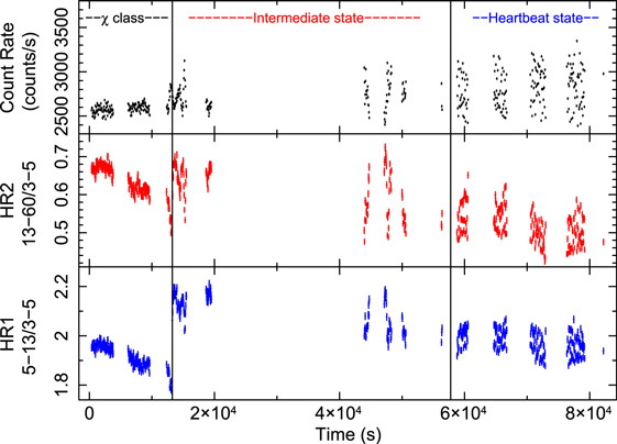
Figure 1. A 50 s binned complete light curve of GRS 1915 + 105 in 3.0–60.0 keV energy range (top panel) combining LAXPC10, LAXPC20, and LAXPC30, hard color (middle panel) and soft color is shown as a function of time.
Download figure:
Standard image High-resolution image
Figure 2. Left panel shows the CCD during three states where the hard color (HR2) is plotted against the soft color (HR1). We have used first ∼1000 s light curve of both χ class and IMS state and last ∼500 s light curve of HS for producing the CCD. Right panel shows hardness–intensity diagram where X-ray intensity in 3–60 keV is plotted against the hard color combining all LAXPC units. A 10 s binned light curve is used for producing the plots.
Download figure:
Standard image High-resolution imageTable 1. LAXPC Observation Details of GRS 1915 + 105
| Orbit Number | State | Effective Exposure (s) | Average Count Rate (3.0–80.0 keV) | Light curve Fractional rms (%) |
|---|---|---|---|---|
| 8107 | χ class | 3793 | 2562 ± 0.9 | 3.3 ± 0.1 |
| 8108 | χ class | 4059 | 2572 ± 0.9 | 3.2 ± 0.1 |
| 8109 | χ class | 4569 | 2619 ± 0.9 | 3.7 ± 0.1 |
| 8110 | IMS | 4325 | 2689 ± 0.9 | 6.1 ± 0.2 |
| 8115 | IMS | 2971 | 2768 ± 1.1 | 6.8 ± 0.3 |
| 8118 | HS | 2053 | 2769 ± 1.3 | 10.0 ± 0.5 |
| 8119 | HS | 2198 | 2776 ± 1.2 | 9.0 ± 0.4 |
| 8120 | HS | 2621 | 2878 ± 1.2 | 11.7 ± 0.5 |
| 8121 | HS | 3195 | 2836 ± 1.1 | 13.8 ± 0.6 |
Note. IMS and HS stand for intermediate and heartbeat state, respectively. Average count rate is calculated combining all three LAXPC units. Light curve fractional rms is calculated using lcstats binned at an interval of 10.0 s combining all LAXPC units.
Download table as: ASCIITypeset image
To check the presence of QPO in the light curve, we extract the power density spectrum (PDS) for the three states χ class, IMS, and HS. The light curve is segmented into 24 segments, where each segment is binned at 8.39 ms and consists of 16,384 points. Fourier transform of an individual segment is calculated and averaged over all segments. Rebinning of the resultant power spectrum in frequency space is done. All PDSs are dead time-corrected (assuming a dead time of 42 μs), and Poisson noise has been estimated and subtracted (for details see Yadav et al. 2016b; Misra et al. 2017). The PDSs are normalized such that its integral over frequency equals the fractional rms squared. Furthermore, the PDSs are corrected for the corresponding background rates (Yadav et al. 2016b).
To study the behavior of the time series as a function of energy, we determine the time lag as a function of photon energy. We also determine the fractional rms as a function of energy for the QPO and the harmonic component for χ class and IMS, respectively. As we shall see, the harmonic component is not present in HS. Hence, in this case, we determine the time lag as a function of energy for the LF QPO and millihertz QPO. Eight energy bands (3.0–4.0, 4.0–5.0, 5.0–7.0, 7.0–9.0, 9.0–12.0, 12.0–15.0, 15.0–20.0 and 20.0–30.0 keV) are used for calculating the time lag. Here, 3.0–4.0 keV band is the reference energy band and the Fourier frequency is binned at an interval of 0.78 Hz and 1.25 mHz for LF QPO and millihertz QPO, respectively. Energy-dependent time lag and rms among different energy bands are computed following Nowak et al. (1999).
We also determine the time lag between 3–5 keV and 9–12 keV photons as a function of Fourier frequency using the LAXPC10 and LAXPC20 separately for the χ class, IMS, and HS. We use both LAXPC10 and LAXPC20 data independently to check the consistency between the two detectors. The Fourier frequency is binned at an interval of 0.6 Hz and 2.5 mHz for the 1–16 Hz and 0.003–0.02 Hz frequency ranges, respectively.
3. Results
In Table 1 we show various parameters for the three states orbitwise. It shows that the light curve fractional rms is increasing steadily from χ class to HS. The left panel of Figure 2 reveals some very important details about the evolution of the source from χ class to HS. When the source evolves from χ class to IMS, accretion disk temperature increases, as indicated by the increase in HR1. However, we see that HR2 is remaining practically unchanged during this transition. In its evolution from IMS to HS, we find that the source moves along the diagonal spread (of data points) toward lower values of HR1 and HR2. For the IMS, data points in the CCD plot occupy a position with a higher value of HR1 as compared with χ class and HS. From the right panel of Figure 2, an overall decline in the hard color value is observed with time, which emphasizes the fact that the source is making a transition from a harder to a softer state. Below, we explore the properties of the individual states.
3.1. χ Class
The top left and right panels of Figure 3 show a 1000 s light curve of χ class in 3.0–5.0 keV and 13.0–60.0 keV energy range, respectively. We may see that X-ray flux level is smaller by a factor of 1.5 in the hard-energy band as compared to the soft energy band. A short time variability of <10 s is seen, but no long-term variability (∼100 s) is observed in the light curve of this class. The PDSs for χ class fitted using Lorentzians in soft (3.0–5.0) and hard (13.0–60.0) energy bands are shown in the bottom left and the bottom right panel of Figure 3. A QPO and harmonic component at ∼3.6 Hz and ∼7.2 Hz is observed in the PDS of χ class for the soft band only. The harmonic component is not significant in 13.0–60.0 keV band. The QPO parameters for all the states and three energy bands (3.0–5.0, 5.0–13.0, and 13.0–60.0 keV) are given in Tables 2–4. Two broad Lorentzian noise components and one subharmonic component are also observed in PDS. As shown in Tables 2–4 a higher value of QPO fractional rms in 5.0–13.0 keV and 13.0–60.0 keV as compared to 3.0–5.0 keV is noticed for all three states.

Figure 3. A 1000 s light curve for χ class is shown in 3.0–5.0 and 13.0–60.0 keV energy range in top left and top right panels, respectively, using a bin time of 2 s combining all LAXPC units. Bottom panel shows the back ground-corrected, Poisson noise-subtracted PDSs for χ class in 3.0–5.0 keV and 13.0–60.0 keV energy range fitted with multiple Lorentzians.
Download figure:
Standard image High-resolution imageTable 2. QPO Parameters for GRS 1915 + 105 in 3.0–5.0 keV Energy Range
| Orbit Number | State | QPO Frequency | QPO Width | QPO Fractional | Harmonic | Width | Fractional rms | (0.0006–20) Hz |
|---|---|---|---|---|---|---|---|---|
| (Hz) | (Hz) | rms (%) | Frequency(Hz) | (Hz) | (%) | Total rms % | ||
| 8107 | χ class | 3.57 ± 0.01 | 0.56 ± 0.04 | 5.7 ± 0.1 | 7.21 ± 0.06 | 1.66 ± 0.20 | 4.0 ± 0.3 | 21.1 ± 0.6 |
| 8108 | χ class | 3.48 ± 0.01 | 0.59 ± 0.03 | 5.7 ± 0.1 | 7.02 ± 0.06 | 1.53 ± 0.23 | 3.6 ± 0.3 | 20.5 ± 0.5 |
| 8109 | χ class | 3.77 ± 0.01 | 0.63 ± 0.04 | 5.9 ± 0.2 | 7.67 ± 0.05 | 1.65 ± 0.20 | 3.7 ± 0.3 | 21.3 ± 0.7 |
| 8110 | IMS | 4.16 ± 0.01 | 0.86 ± 0.05 | 5.8 ± 0.2 | 8.28 ± 0.13 | 3.11 ± 0.51 | 3.6 ± 0.3 | 23.8 ± 1.5 |
| 8115 | IMS | 4.95 ± 0.04 | 1.22 ± 0.11 | 5.1 ± 0.2 | 9.96 ± 0.31 | 5.83 ± 1.68 | 4.0 ± 0.2 | 23.2 ± 2.3 |
| 8118 | HS | 4.97 ± 0.05 | 1.26 ± 0.14 | 4.3 ± 0.1 | 10.13 ± 0.31 | 5.14 ± 1.60 | 3.9 ± 0.4 | 24.0 ± 2.5 |
| 8119 | HS | 5.05 ± 0.04 | 1.18 ± 0.13 | 4.5 ± 0.2 | 10.27 ± 0.47 | 5.47 ± 1.49 | 3.4 ± 0.4 | 24.0 ± 3.6 |
| 8120 | HS | 5.40 ± 0.04 | 1.21 ± 0.11 | 4.2 ± 0.1 | 10.36 ± 0.75 | 10.33 ± 2.73 | 3.8 ± 0.4 | 33.4 ± 2.3 |
| 8121 | HS | 5.32 ± 0.05 | 1.51 ± 0.15 | 4.3 ± 0.2 | 9.82 ± 0.63 | 8.97 ± 2.25 | 4.10 ± 0.4 | 36.4 ± 2.9 |
Download table as: ASCIITypeset image
Table 3. QPO Parameters for GRS 1915 + 105 in 5.0–13.0 keV Energy Range
| Orbit Number | State | QPO Frequency | QPO Width | QPO Fractional | Harmonic | Width | Fractional rms | (0.0006–20) Hz |
|---|---|---|---|---|---|---|---|---|
| (Hz) | (Hz) | rms (%) | Frequency (Hz) | (Hz) | (%) | Total rms% | ||
| 8107 | χ class | 3.60 ± 0.01 | 0.63 ± 0.03 | 8.6 ± 0.1 | 7.07 ± 0.04 | 1.55 ± 0.12 | 4.1 ± 0.1 | 28.0 ± 0.5 |
| 8108 | χ class | 3.51 ± 0.01 | 0.65 ± 0.03 | 8.7 ± 0.1 | 6.90 ± 0.03 | 1.12 ± 0.11 | 3.7 ± 0.1 | 28.0 ± 1.3 |
| 8109 | χ class | 3.81 ± 0.01 | 0.70 ± 0.03 | 8.8 ± 0.1 | 7.48 ± 0.05 | 1.79 ± 0.19 | 3.9 ± 0.1 | 27.2 ± 0.7 |
| 8110 | IMS | 4.21 ± 0.01 | 0.93 ± 0.04 | 8.5 ± 0.2 | 8.44 ± 0.06 | 2.27 ± 0.19 | 3.7 ± 0.1 | 32.7 ± 1.9 |
| 8115 | IMS | 4.87 ± 0.02 | 1.32 ± 0.07 | 7.8 ± 0.2 | 9.51 ± 0.16 | 4.92 ± 0.72 | 4.3 ± 0.5 | 30.0 ± 1.8 |
| 8118 | HS | 4.99 ± 0.03 | 1.48 ± 0.08 | 7.5 ± 0.2 | 8.96 ± 0.46 | 10.30 ± 0.77 | 6.7 ± 0.2 | 29.9 ± 3.1 |
| 8119 | HS | 5.05 ± 0.02 | 1.33 ± 0.08 | 7.5 ± 0.1 | 9.07 ± 0.47 | 10.87 ± 0.85 | 6.6 ± 0.2 | 34.7 ± 2.3 |
| 8120 | HS | 5.47 ± 0.02 | 1.42 ± 0.06 | 7.0 ± 0.1 | 10.72 ± 0.30 | 9.69 ± 0.84 | 5.4 ± 0.1 | 34.5 ± 2.3 |
| 8121 | HS | 5.35 ± 0.02 | 1.41 ± 0.05 | 7.0 ± 0.1 | 8.96 ± 0.46 | 9.85 ± 0.73 | 5.8 ± 0.1 | 40.1 ± 2.9 |
Download table as: ASCIITypeset image
Table 4. QPO Parameters for GRS 1915 + 105 in 13.0–60.0 keV Energy Range
| Orbit Number | State | QPO Frequency | QPO Width | QPO Fractional | Harmonic | Width | Fractional rms | (0.0006–20) Hz |
|---|---|---|---|---|---|---|---|---|
| (Hz) | (Hz) | rms (%) | Frequency (Hz) | (Hz) | (%) | Total rms % | ||
| 8107 | χ class | 3.60 ± 0.01 | 0.56 ± 0.05 | 7.6 ± 0.4 | ⋯ | ⋯ | ⋯ | 29.2 ± 1.6 |
| 8108 | χ class | 3.48 ± 0.01 | 0.58 ± 0.05 | 8.1 ± 0.4 | ⋯ | ⋯ | ⋯ | 29.9 ± 2.1 |
| 8109 | χ class | 3.75 ± 0.02 | 0.55 ± 0.06 | 6.9 ± 0.5 | ⋯ | ⋯ | ⋯ | 28.1 ± 2.3 |
| 8110 | IMS | 4.23 ± 0.02 | 0.99 ± 0.08 | 8.2 ± 0.2 | ⋯ | ⋯ | ⋯ | 32.6 ± 2.5 |
| 8115 | IMS | 4.92 ± 0.03 | 0.89 ± 0.16 | 6.0 ± 0.5 | ⋯ | ⋯ | ⋯ | 28.6 ± 3.7 |
| 8118 | HS | 4.98 ± 0.05 | 1.23 ± 0.15 | 4.2 ± 0.2 | ⋯ | ⋯ | ⋯ | 26.9 ± 1.7 |
| 8119 | HS | 5.01 ± 0.05 | 1.20 ± 0.14 | 6.8 ± 0.5 | ⋯ | ⋯ | ⋯ | 29.7 ± 2.0 |
| 8120 | HS | 5.49 ± 0.04 | 1.68 ± 0.12 | 7.5 ± 0.2 | ⋯ | ⋯ | ⋯ | 30.2 ± 2.2 |
| 8121 | HS | 5.31 ± 0.03 | 1.45 ± 0.12 | 7.3 ± 0.3 | ⋯ | ⋯ | ⋯ | 30.2 ± 2.5 |
Download table as: ASCIITypeset image
In the top left panel of Figure 4, a decrease in the time lag at the higher energy band implies soft lag at the QPO frequency of ∼3.6 Hz. On the other hand, at the harmonic frequency of ∼7.2 Hz, a characteristic hard lag is observed. Although the reason is not clear, the time lag at a given energy band is higher at the harmonic frequency compared to that of the QPO frequency. This implies that the phase lag between two given energy bands is different at the QPO and harmonic frequencies.
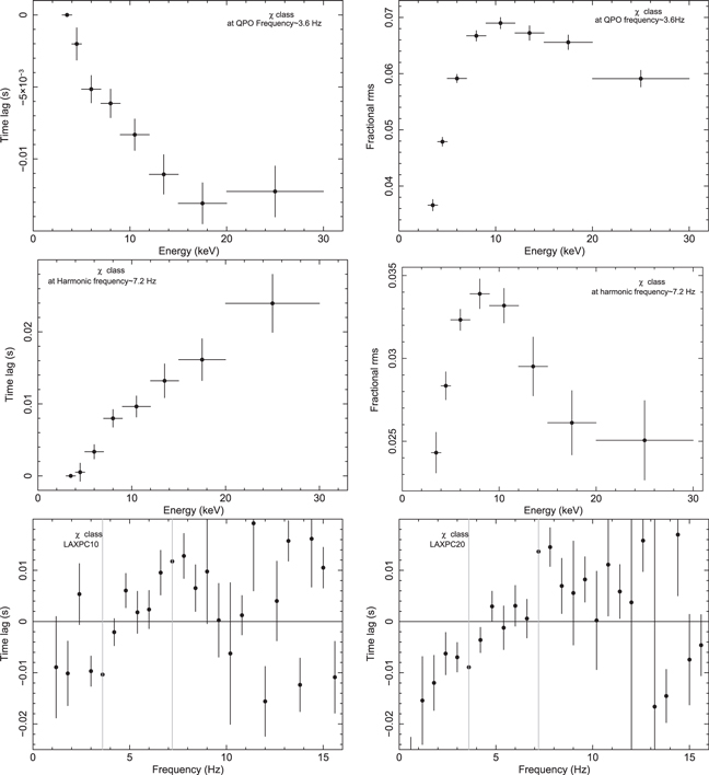
Figure 4. Time lag as a function of photon energy is shown at the QPO frequency ∼ 3.6 Hz (top left) and the harmonic frequency ∼7.2 Hz (middle left) during the χ class combining all LAXPC units. Fractional rms as a function of photon energy is shown at the QPO frequency ∼ 3.6 Hz (top right) and the harmonic frequency ∼7.2 Hz (middle right) combining all LAXPC units. The time lag between 3–5 keV and 9–12 keV as a function of Fourier frequency is shown in the bottom left and bottom right panels for LAXPC10 and LAXPC20, respectively. Vertical gray lines in both panels show the position of the QPO and its harmonic.
Download figure:
Standard image High-resolution imageThe strength of the QPO and harmonic component also varies with photon energy, as shown in the top right and middle right panels, respectively, in Figure 4. For QPO, the fractional rms rises to ∼7% and attains its maximum value at 9.0–12.0 keV energy band and decreases later to 5.5%. For the harmonic, the rms value reaches its maximum of ∼3.5% in 9.0–12.0 keV band and reduces significantly at higher energies. The reduction in the rms value of harmonic above 12.0 keV is the result of the absence of a harmonic component in hard-energy band (13.0–60.0 keV). In the bottom panels of Figure 4, we see that the time lag increases from the soft lag at the lower frequency and makes a transition to the hard lag at a frequency of ∼5.5 Hz. Two dotted lines are marked at QPO and the harmonic frequency, highlighting the fact that the time lag is negative for QPO and becomes positive for the harmonic component, which is in agreement with the time-lag spectra shown in top panels of Figure 4.
3.2. Intermediate State
The top left and right panels of Figure 5 show 3 ks light curve of the IMS, with a 2.0 s bin size in two different energy ranges, 3.0–5.0 keV and 13.0–60.0 keV, respectively. To account for the variability in the IMS, we extract PDS in the 3.0–5.0 keV and 13.0–60.0 keV energy ranges. These are shown in the bottom left and bottom right panels of Figure 5, respectively. We fit the PDS with five Lorentzians: the QPO, harmonic, subharmonic, and two broad noise components.
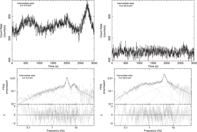
Figure 5. A ∼3000 s section of the IMS light curve is shown in 3.0–5.0 and 13.0–60.0 keV energy ranges in the top left and top right panels, respectively, using a bin time of 2 s combining all LAXPC units. The bottom panels show the PDSs for the IMS in 3.0–5.0 keV and 13.0–60.0 keV energy range fitted with multiple Lorentzians.
Download figure:
Standard image High-resolution imageThe time-lag and rms spectra shown in Figure 6 show a similar trend as observed for the χ class. However, the fractional rms values at different energy bands are less than those observed during the χ class. In bottom panels of Figure 6, we observe a soft lag up to 6 Hz and then the lag changes sign and becomes hard lag up to ∼9 Hz. This is similar to the behavior of the χ class and independently observed from LAXPC10 (bottom left panel) and LAXPC20 (bottom right panel), respectively. The dotted lines mark the QPO frequency (∼4.0 Hz) and the harmonic component (∼7.8 Hz) showing the soft lag and the hard lag for the QPO and harmonic component, respectively.
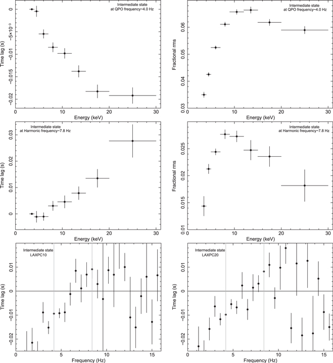
Figure 6. Time lags as a function of photon energy are shown at the QPO frequency ∼4.0 Hz (top left) and the harmonic frequency ∼7.8 Hz (middle left) during the IMS combining all LAXPC units. Fractional rms as a function of photon energy is shown at the QPO frequency ∼3.6 Hz (top right) and the harmonic frequency ∼7.8 Hz (middle right) during the same combining all LAXPC units. The time lag between 3–5 keV and 9–12 keV as a function of Fourier frequency is shown in the bottom left and bottom right panels for LAXPC10 and LAXPC20, respectively. Vertical gray lines in both panels show the position of the QPO and its harmonic.
Download figure:
Standard image High-resolution image3.3. Heartbeat State
The top left panel of Figure 7 illustrates ∼1100 s light curve of the HS in 3.0–5.0 keV energy band where a peculiar behavior can be noticed. As the source evolves, a sequence of alternately high and low peak count rate is observed where peak count rate changes by a factor of ∼1.5 in every 100 s. The light curve profile of the same section in 13–60 keV energy range is shown in the top right panel of Figure 7. The high count rate peak followed by a low count rate peak structure is absent in the hard band (13–60 keV). A detailed investigation reveals that the cycle period of the flares decreases from ∼150 s to ∼100 s in ∼20 ks HS observation. Moreover, the peak count rate of flares also increases and the dip count rate decreases. The bottom left and right panels of Figure 7 show the PDS for the HS in the Fourier frequency range of 1 mHz to 2 Hz in the soft and hard bands, respectively. Two QPOs are clearly visible: one due to the large-amplitude cyclic variation observed in light curve with the QPO frequency of ∼5 mHz and another at a frequency of ∼5 Hz, similar to that observed from χ class and IMS. We see that the fractional rms for the millihertz QPO is smaller in the hard band in comparison to the soft band, whereas an opposite behavior is seen for the LF QPO.
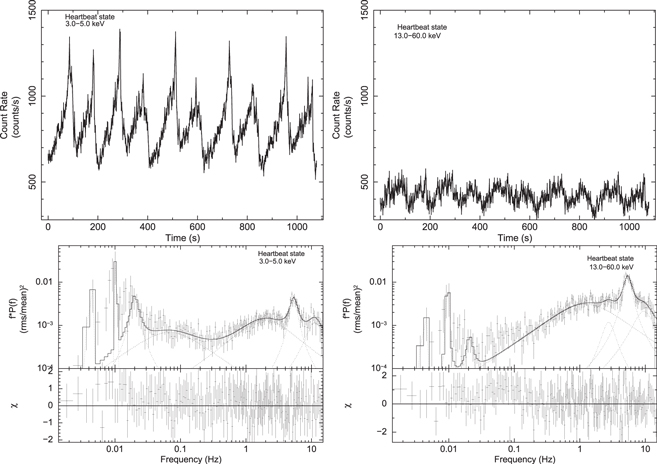
Figure 7. A 1100 s light curve of the HS in 3.0–5.0 keV energy range when alternate high-flux, pulsed, and low-flux peaked flares are observed systematically shown in top left panel. Top right panel shows the similar section but in the energy range 13–60 keV. The light curves are generated combining LAXPC10, LAXPC20, and LAXPC30 units. Bottom panels show the power density spectra for the HS state in 3.0–5.0.0 keV and 13.0–60.0 keV energy range fitted with multiple Lorentzians.
Download figure:
Standard image High-resolution imageTo further confirm the spectral nature of the alternative profiles in the soft band, we plot the light curve, hard color (HR2), and soft color (HR1) as a function of time in Figure 8. A dip in HR2 is observed exactly at the time when the count rate reaches its maxima. This implies that the spike in the light curve is a soft pulse. A time delay of 10–15 s is observed between the peak of HR1 and peak of light curve. The implications of such results are provided in the discussion section. In the HID plot of HS (Figure 2 right panel), we do not observe a loop-like structure as observed by Altamirano et al. (2011) during the ρ class of GRS 1915 + 105 and IGR J17091-3624. However, we can anticipate such behavior from Figure 8 where the peak of the HS light curve profile exactly corresponds to the minimum of the hard color. The anticorrelation between X-ray count rate and the hard color is observed as expected with zero time delay between X-ray count rate and the hard color.
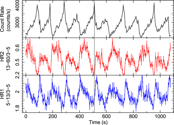
Figure 8. HS light curve in the 3–60 keV band with alternate large pulse and peaked flares (top panel) is shown along with the hard color (HR2; middle panel) and soft color (HR1; bottom panel) as a function of time using all LAXPC units. A vertical gray line is drawn along all three panels at the position of large pulse so that corresponding HR2 and HR1 can be noted.
Download figure:
Standard image High-resolution imageThe left panel of Figure 9 shows PDS of the HS in the frequency range between 550 microhertz and 10 Hz. The PDS during the end of the HS observation (76–82 ks in Figure 1) shows the QPO peak and its harmonic. A zoomed view (right panel of Figure 9) of LF QPO ∼5 Hz in three different times of observation shows that the peak of the QPO frequency does not vary within the HS. However, the shape changes. During the last orbit of HS observation (76–82 ks), we notice a broad, distorted, and asymmetric profile for LF QPO, whereas two peaks in the profile structure of millihertz QPO become more prominent. However, it is not clear whether the distortion and broadening in the QPO profile are caused by changes in QPO frequency with time or the presence of two QPOs separated by a small frequency interval that we cannot resolve.
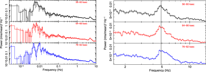
Figure 9. Left panel shows PDSs of the HS in the frequency range 500 μHz to 10 Hz (energy range 3–80 keV) during three different orbits: at the beginning of the HS cycle (top panel), at the middle of the HS (middle panel), and at the end of the HS (bottom panel). Strong QPOs due to cyclic behavior and LF QPO at ∼6 mHz and ∼5 Hz can be observed clearly. Zoomed views of ∼5 Hz QPO during same three orbits are shown in the right panel.
Download figure:
Standard image High-resolution imageTime lag as a function of photon energy for the QPO at ∼5.0 Hz is plotted in the left panel of Figure 10, whereas the right panel shows the fractional rms spectra for the same QPO. Similar to χ class and IMS, the lag spectra show a soft lag, whereas the fractional rms increases with energy. The energy-dependent time-lag spectra and the rms spectra at the Fourier frequency of 5 mHz are shown in the upper middle left and upper middle right panels of Figure 10. The energy-dependent lag spectra show hard lags up to ∼6 keV and soft lags at higher energy. However, the rms spectra show the opposite behavior. During the HS, the fractional rms strictly decreases with energy, whereas the energy-dependent fractional rms during the ρ class either increases with energy or initially increases up to ∼10 keV and then decreases (Mir et al. 2016). The time lag versus frequency plot shows the same behavior at QPO (∼5.0 Hz) and harmonic frequency as observed in χ class and IMS. The bottom left and bottom right panels of Figure 10 show the time lag of the 5.0–13.0 keV energy band with respect to 3.0–5.0 keV band (black data points), 13.0–60.0 keV band with respect to 3.0–5.0 keV band (red data points), and 13.0–60.0 with respect to 5.0–13.0 keV photons (blue data points) as a function of Fourier frequency for LAXPC10 and LAXPC20, respectively, at the QPO frequency ∼5 mHz. For the 13.0–60.0 keV band, a soft lag is observed with respect to both 3.0–5.0 keV and 5.0–13.0 keV bands for millihertz QPO. In contrast, the lag is very small for 5.0–13.0 keV relative 3.0–5.0 keV band at millihertz QPO frequency.
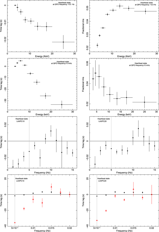
Figure 10. Top left and top right panels show time lag and fractional rms as a function of photon energy at the LF QPO frequency ∼5 Hz during the HS using all LAXPC units. Upper middle left and upper middle right panels show the energy-dependent time lag and fractional rms at millihertz QPO frequency. A time lag of 9.0–12.0 keV photons with respect to 3.0–5.0 keV photons as a function of frequency is plotted for LAXPC10 and LAXPC20 in the lower middle left and lower middle right panels, respectively. The lag at the QPO frequency of ∼5 Hz is shown by a vertical gray line. The bottom panels show time lag as a function of frequency for the energy band 5.0–13.0 keV relative to the band 3.0–5.0 keV (black colored data points), 13.0–60.0 keV band relative to 3.0–5.0 keV band (red color data points), and 13.0–60.0 keV band relative to 5.0–13.0 keV band (blue color data points).
Download figure:
Standard image High-resolution image3.4. Dynamic Power Spectra
To check the time-dependent behavior of the QPOs in different states, we computed the dynamic power spectrum (DPS). We plot the DPSs for χ class (left panel), IMS (middle panel), and HS (right panel) in the energy range 3–80 keV and frequency interval 2.5–7.0 Hz in Figure 11. During χ class, we observe the peak of the QPO frequency at ∼3.5 Hz nearly constant in time. However, the rms power of QPO shows some variation with time. In contrast, a systematic variation in the QPO frequency between 3.5 and 4.5 Hz has been observed in the DPS of IMS. Moreover, we also see systematic variations in the strength of the QPO. When the QPO frequency shifts to the highest value, the rms power decreases, whereas the rms power is highest close to the minimum of the QPO frequency. During both cycles, each having a period of ∼1500 s, the rms power changes by a factor of ∼2. Double cyclic change is observed in both QPO frequency and the rms of the QPO in an anticorrelated manner. However, we do not see any cyclic pattern in the DPS when the source transits from the IMS to HS. As observed from the plot, the QPO frequency changes between 5.5 and 4.5 Hz in 2000 s; however, the rms does not change significantly in this timescale. Interestingly, the peak rms power of the HS is smaller by a factor of ∼2 when compared to that of χ class and IMS.
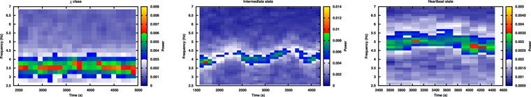
Figure 11. 3–30 keV DPSs during the χ class (left panel), IMS (middle panel), and HS (right panel) are shown in the frequency range 2.5–7 Hz. A gradual increase in the QPO frequency and its time-dependent behavior is clearly observed from three panels.
Download figure:
Standard image High-resolution image4. Discussions
In this work, we present the continuous monitoring of GRS 1915 + 105 (∼90 ks) using AstroSat/LAXPC when a weak-to-strong variability transition is observed in X-rays. A HID plotted for the entire observation shows a gradual transition from the spectrally hard to a spectrally softer state (Figure 2). Three different states in the CCD are distinguishable from each other (right panel of Figure 2). During the first few tens of kiloseconds, the source shows no large-amplitude, long-timescale (few tens of seconds) variabilities in both soft (3–5 keV) and hard (13–60 keV) X-ray light curves. This variability is similar to the radio-quiet χ class (χRQ ). The PDS in the soft band reveals the presence of a strong LF QPO at ∼3.6 Hz and its harmonic at ∼7.2 Hz. However, in the hard band, the harmonic component is not significant. We computed the time-lag spectra and the fractional rms spectra as a function of photon energy at the QPO and harmonic frequencies. The time delay spectra show the soft lag trend at the QPO, whereas at the harmonic frequency, we observe the hard lag.
4.1. Comparison Between Observed χ Class and Other Subclasses of the χ Class
Using a radio/X-ray joint monitoring program, Rodriguez et al. (2008b) observed that the 15 GHz radio flux density during χ X-ray class gradually changed from a radio-quiet state with a mean level of ∼44.9 mJy to a radio-loud state with a mean level of ∼70.4 mJy. Later Pahari et al. (2013) showed that the radio flux density during the radio-quiet χ class can be as low as 10 mJy or less. Although the classification is based on the radio flux density, the X-ray spectral and timing properties of the radio-quiet and the radio-loud χ class are remarkably different. Although no simultaneous radio observation was performed with the AstroSat observation of the χ class presented here, we observed that the X-ray timing properties, such as the QPO frequencies and strength, the nature of light curve, CCD, HID, and lag spectra of the χ class observation analyzed in this work are remarkably similar to the radio-quiet χ class and dissimilar to the radio-loud χ class. We discuss them below. During the radio-loud χ class (plateau state), no phase reversal is observed between the QPO and the harmonic frequencies in GRS 1915 + 105 when QPOs are observed at a frequency lower than 2 Hz (Trudolyubov 2001; Yadav 2006; Pahari et al. 2013). On the other hand, during the radio-quiet χ class as observed by Pahari et al. (2013), phase reversal is noticed during the QPO and the harmonic frequencies, and QPOs are observed at a frequency similar to that observed during our present χ class observations. We also notice phase reversal in the lag spectra. However, there are differences between the χ class observed here and other subclasses of the χ class. During the χ class, we observe an additional strong LF broad Lorentzian noise component at a frequency of ∼0.25 Hz, which is absent from the PDS of the radio-quiet χ class in GRS 1915 + 105 observed with AstroSat/LAXPC (Yadav et al. 2016b) and RXTE/PCA (Pahari et al. 2013). Second, for the QPO component, the time-lag spectra of the χ class show a soft lag accompanied by sharp upturn at 20 keV, above which it shows a hard lag (Yadav et al. 2016b). In the present analysis, we do not observe any hint of an upturn in the time-lag spectra for the QPO component at higher energies in the χ class. Because of its high efficiency, LAXPC is able to resolve more complex structure in the PDS at different photon energies and is able to constrain lag spectra at harder X-ray band than can RXTE/PCA. Therefore, such differences can be attributed to the high detection efficiency of LAXPC compared to RXTE/PCA, particularly in the harder band. It may be noted that, during the χ class, the 3.0–80.0 keV X-ray intensity using LAXPC10 is ∼860 counts/s, whereas it was much higher(>2000 counts/s) in earlier observed radio-quiet χ class using AstroSat/LAXPC (Yadav et al. 2016b).
4.2. Transition Phase
At the end of the χ class, marked by the sudden increase and strong variability in the hardness (bottom panel of Figure 1), we note that a long-term, large-amplitude, irregular variability is introduced in the light curve (top left panel of Figure 5). Such variability on the timescale of a few thousands of seconds is observed only in the soft X-ray band (3–5 keV) but is absent from the hard X-ray band light curve (13–60 keV). We termed it as “IMS.” The large-amplitude, long-timescale, irregular variability in the soft X-rays is possibly linked to the onset of an outer disk (>50 Rg) turbulence caused by the fluctuations in the mass accretion rate (Neilsen et al. 2011). Despite large-amplitude fluctuations, it is interesting to note that the PDS of IMS shows the LF QPO at ∼4 Hz and its harmonic, whereas the QPO frequency is slightly higher than that observed during the χ class. The strength of the QPO and its harmonic during both IMS and χ class are similar. Moreover, the time-lag spectra of IMS and χ class are also very similar to each other. The reduced fractional rms values in IMS in comparison to those observed during the χ class may imply that, with the launch of large-amplitude, irregular flares, the strength of the QPO is reduced. Comparing hard X-ray light curve of χ class and IMS, we may note that the hard X-ray HR2 remains the same for both states, whereas HR1 attains the highest value in IMS. From the DPS, we may note that, during IMS, the LF QPO surprisingly disappears during certain time intervals. The time-averaged QPO frequency, rms, and width of the observed LF QPOs are similar to those of type-C QPOs. However, the type-C QPOs are found to be very stable for other X-ray binaries, in contrast to our observations. We speculate that the quasi-appearance and disappearance of type-C QPOs during IMS may be caused by the inner disk perturbation driven by the large-amplitude, slow outer disk variability.
4.3. Heartbeat State—Similarities and Dissimilarities with Classical  Class
Class

Immediately after the IMS, semiregular periodic fluctuations have been observed during the last phase (∼20 ks) of our observations. We termed it as the “HS” for the following reasons. The variability profile is highly structured and has a significant resemblance to the “ρ” class/heartbeat oscillations in GRS 1915 + 105 (Yadav et al. 1999; Belloni et al. 2000; Neilsen et al. 2011). For example, during the HS in our observation, the ratio of maximum-to-minimum flux, averaged over ten cycles, increases from ∼1.5 to ∼2.1 with time, whereas the same during a typical ρ class changes from ∼1.73 to ∼3.33 with time. Although the trend is the same, the values are different. Because these ratios are instrument-independent, a lower ratio during our observation implies that the light curve variability is not fully evolved to a classical ρ class. A similar trend but difference in the evolution of cycle timescale values are observed between the HS and typical ρ class. During HS, the cycle timescale (∼150 s) in the first few kiloseconds is found to be longer than that during last few kiloseconds of observations (∼100 s), which is shown in the top panel of Figure 8. An evolution of ρ cycles toward faster timescale is also observed from GRS 1915 + 105 (110–40 s) and another black hole X-ray transient IGR J17091-3624 (50–20 s) (Pahari et al. 2014). However, in both cases, the evolution started from a large cycle period and evolved up to about half of its value (Figure 6 and Table 3 in Pahari et al. 2014). Such offset in values with similar trends implies that, given a sufficient time to evolve, the HS state variability will eventually lead to the ρ class. It may also be noted that each flare in ρ class shows two peaks when its time cycle is fast (e.g., the 50 s cycle time for GRS 1915+105; Figure 7 in Pahari et al. 2014). In our observation of HS, it is usually a single peak with a time cycle >100 s. We also observe a variation in the alternate peak count rate as shown in top left panel of Figure 7. Such a behavior is seen for the first time in GRS 1915 + 105. Therefore, we observe here an evolution of the large-amplitude, systematic variability that leads to the onset of the heartbeat oscillations in GRS 1915 + 105. Hence, the HS stage can be considered as the precursor of the heartbeat oscillations. We observe a steady increase in light curve fractional rms from χ class to HS as shown in Table 1. This can be attributed to the long-term variability in the light curve.
Despite few similarities in the evolution trend, a few interesting differences between the HS and the ρ class/heartbeat oscillations are noteworthy. We observe a single-peaked pulse during the HS. However, the flux during the pulse peak changes by a factor of ∼1.4 in alternate peaks shown in the top panel of Figure 8. Such a large and systematic change in flux in alternative peaks has not been reported for typical ρ class observations. The nature of the hard color (HR2) and the soft color (HR1) during single-peaked pulse in ρ class is shown by Neilsen et al. (2012). At the position of the pulse peak, shown in their Figure 1, HR2 shows a sudden dip while HR1 shows a sharp peak. This is expected because the pulse is soft. Although the position of the HR2 dip of the pulse during our HS observation in the middle panel of Figure 8 matches with that from Neilsen et al. (2012), the position of HR1 shows a clear discrepancy by 15–20 s. The energy-dependent lag spectra at the millihertz QPO frequency shown in the upper middle left panel of Figure 10 also exhibits a peculiar trend of hard lag of the order of few seconds up to 6 keV and then a soft lag of the order of few tens of seconds at harder X-ray bands. Similar behavior has also been observed from the RXTE/PCA time-lag spectra of ρ class in GRS 1915 + 105 at the heartbeat frequency (Mir et al. 2016). The rms spectra for the HS show different behavior in comparison to that observed by Mir et al. (2016) for ρ class. The reason for such a discrepancy is not clear. The lag timescale is so large that it can be accounted neither by the reprocessing nor by the Comptonization timescale. Therefore, propagation of fluctuations in viscous timescale (Uttley et al. 2011) and a delayed response of the inner disk radius in response to fluctuating mass accretion rate as observed by Mir et al. (2016) are suitable for explaining the long lag.
4.4. QPO Evolution in Three States
Although the long-term, large-amplitude component with the variability timescale of the order of few hundreds of seconds significantly evolves from the χ class to HS, the time-averaged LF QPO properties change marginally, as seen in Tables 2–4. In the 3–5 keV energy band, we observe that from the χ class to HS, the LF QPO changes its frequency from ∼3.6 to ∼5.3 Hz, whereas its fractional rms and the width, averaged over few kiloseconds, changes from ∼5.7% to ∼4.3% and ∼0.56 Hz to ∼1.56 Hz, respectively (Table 2). Similar changes are seen in other energy bands. The time-lag spectra show a soft lag during all three states, and the rms spectra are very similar. Therefore, if we assume that the LF QPO is caused by the inner disk activity in a coupled disk-corona system, then the large-amplitude variability may be an outer disk phenomena, and the long-timescale variability does not perturb short timescale variability originating from the inner accretion disk. Such a scenario is also consistent with Neilsen et al. (2011), who assume that the fluctuation during ρ cycles, which causes the density wave that propagates inward, originates at a disk radius of 30 Rg or higher. Interestingly, the harmonic component, which is strongly detected during the χ class and IMS, becomes relatively insignificant during the HS, as can be seen from Figure 7. We also see from Tables 2 and 3 that the width of the harmonic becomes large in the HS, which would lead to a relatively small Q-factor. During the χ class and the IMS, the time-lag and the rms spectra at the harmonic frequency are found to be similar.
5. Summary and Conclusions
- 1.In this article, we present AstroSat observation of a peculiar galactic microquasar GRS 1915 + 105, and, on the basis of change in the variability of X-ray light curve, CCD, and HID plots, we report a state transition from χ class to a HS via an IMS.
- 2.The higher sensitivity and resolution of AstroSat/LAXPC as compared to RXTE/PCA data unveil some new features of χ class. Therefore, with LAXPC we note that the subclasses of the χ class behave differently at different X-ray intensity levels.
- 3.The consistency of PDS, time lag, rms spectral properties, and the hard X-ray flux between χ class and IMS imply that the large variability observed in soft band IMS does not affect the hard X-ray variability. The LF QPOs, corresponding harmonics, and the nature of lag and rms spectra, which are inner accretion properties, remains largely unaffected by such outer disk amplitude modulation.
- 4.An interesting feature that we observe is the transient nature of the C-type QPO during the IMS phase. We find that the DPSs of IMS in the energy range 3.0–30.0 keV (middle panel of Figure 11) show a remarkable evolution of the QPO strength by a factor of ∼2, which is probably driven by the long-term disk fluctuation. We suggest that this may be associated with the inner disk perturbation caused by large-amplitude variation of the outer disk.
- 5.A preliminary time-averaged spectral analysis of the HS, which would be discussed elsewhere, indicates that the Eddington luminosity fraction, defined as the ratio between 0.1 and 100 keV unabsorbed X-ray luminosity to the Eddington luminosity, is ∼0.2–0.25, whereas the same during a typical ρ class is ∼0.7–0.8 (Neilsen et al. 2011, 2012). This indicates that the inner accretion region in a typical ρ class is strongly dominated by the radiation pressure compared to the inner disk during HS. Therefore, the difference in the soft/hard lag behavior between the HS and the ρ class may be attributed to the modifications of the accretion and radiation geometry caused by the strong radiation pressure at the inner disk region. Exploring further in this direction is beyond the scope of the present work.
We thank the referee for constructive suggestions, which were very helpful in improving the article. We thank members of LAXPC instrument team for their contribution to the development of the LAXPC instrument. We also acknowledge the contributions of the AstroSat project team at ISAC. This article makes use of data from the AstroSat mission of the Indian Space Research Organisation (ISRO), archived at the Indian Space Science Data Centre (ISSDC). M.P. acknowledges TIFR for giving him a three month visiting position and the Royal Society-SERB Newton International Fellowship support funded jointly by the Royal Society, UK and the Science and Engineering Board of India (SERB) through Newton-Bhabha Fund.